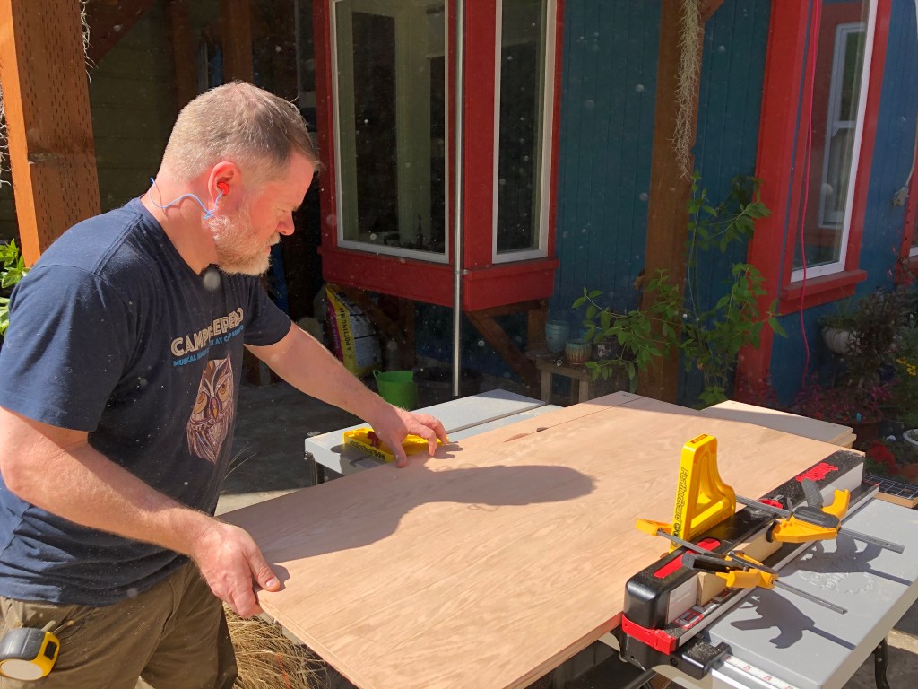
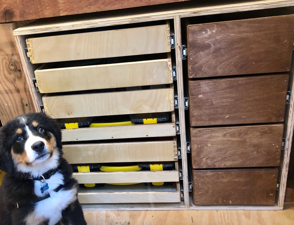
So if there’s a saw, there needs to be a lot of cutting. That’s my theory, anyway, now that I have a fancy new saw. My lab + shop are together 95 square feet, so space is seriously tight. There’s a space 31"T x 33"W x 22"D that could hold more if there were an orderly way to put stuff there. This is new for me, I’ve never built drawers before. Here’s the space with a cabinet frame and a 11-week-old, 14-lbs puppy for perspective.

The key issue that’s motivating this where to put fasteners: bolts, screws, nuts, washers, yes, imperial and metric, but also t-nuts, standoffs, inserts and other tiny bits. Plus drill and router bits. Adam Savage famously stores all the little pieces with the Sortimo system, but the Sortimo boxes are like $65 each, and in Adam’s system, you have to pull the whole box out and put it somewhere in order to dig around looking for some tiny thing.

I don’t think I need the 20-odd boxes Adam has, probably 4-5 would so it. The Stanley organizer box isn’t quite the build quality of the Sortimo but it’s good enough.

And where to put the box when I pull it out of the rack? This turns out to be key. My shop’s flat spaces are always cluttered, and sure, I should get better at not leaving clutter, but practically, a self-supporting drawer would reduce how much I have to pull the boxes in and out. It would be efficient to open a drawer and putter in the drawer without pulling out the box.

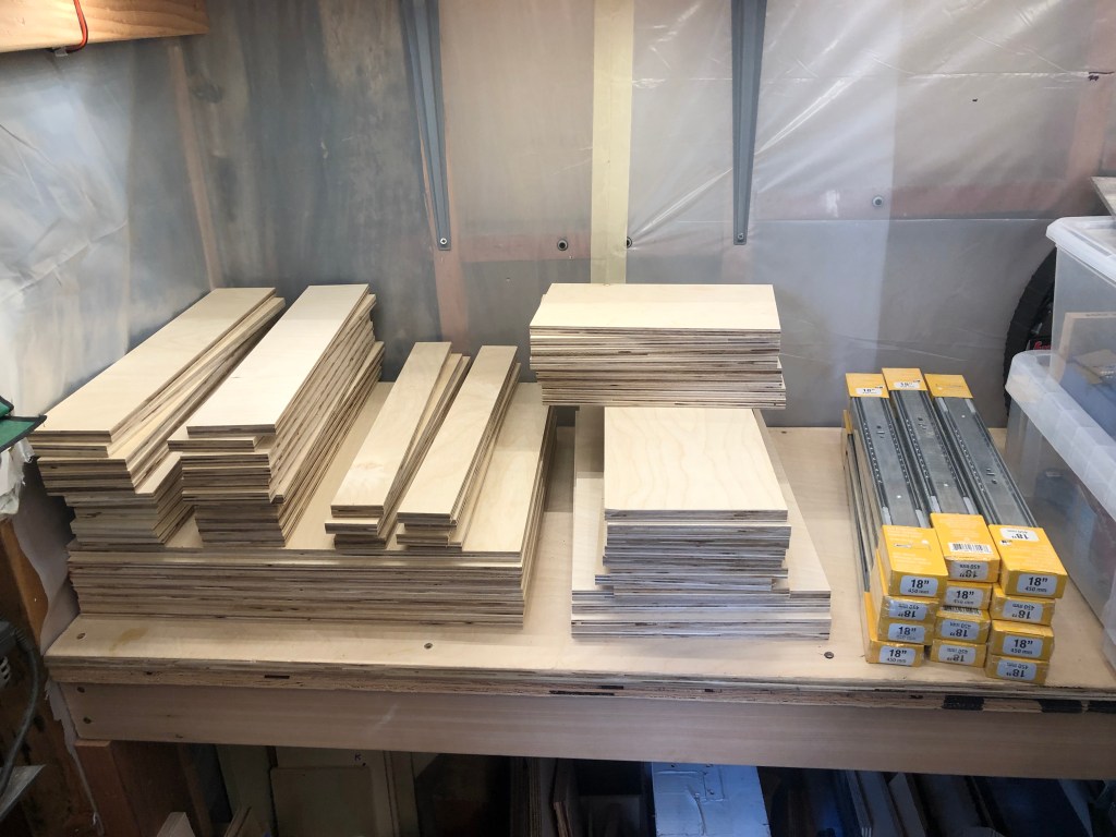
After much drawing, I decided to build 7 drawers in the left column, each xx"W x 3 1/4"T, and 4 drawers in the right column each xx"W x 6 1/2"T. I figured I’d just make butt joints, so the measurements were pretty easy. However, the plywood comes in 4×8′ sheets, and I only have a Toyota Camry sedan. I tried to estimate all the pre-cuts so that I could cut the plywood into useful sizes that would fit into the car at the lumber yard. Needless to say, this was extremely wasteful. I cut a lot of pieces to the wrong size and lost wood, but even more, I lost a lot of time trying to figure it out. Lesson learned #1: have MacBeath Hardwood deliver the full sheets, and only cut them once the final cuts are set.

The upside to all the cutting-at-once is that the pieces are regular. The downside is that if I misunderstood a dimension, or if I change my mind about the joinery or some other build aspect, the cuts are wrong, creating more waste. Of course both happened: I ended up with several different kinds of joinery, and the cuts were wrong. There was a lot of waste.

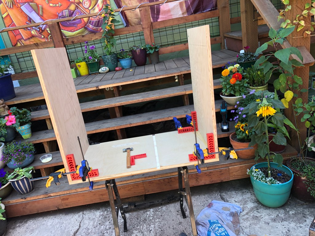
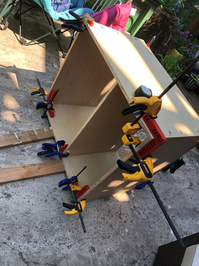
To build the carcase, I just used butt joints. My theory is that the primary weight is on the drawers which will tend to pull the sides and divider down and together. They’re 3/4" plywood, and there’s a 1/4" ply back panel providing rigidity. Everything is glued, pinned, and then screwed through the butt joints. (Ignore the pocket holes which were a screwup. It’s not nearly as rigid as I’d like, it’s got a little bit of flex around the middle axis (imagine that if you’re looking down at it, it can rotate slightly). Some reinforcement might be needed someday.

The original vision was a barely glorified-tray to hold the boxes. However, those looked terrible, and as I kept reading about drawer joinery, the butt joints didn’t seem strong enough: screws driven into the edge of plywood won’t grip well because they’ll tend to separate the plys. Furthermore, glue doesn’t adhere all that well to the plywood’s edges. I built one for completeness, with the 1/2" plywood bottom set inside the sides + front + back, glued, pinned, and screwed.

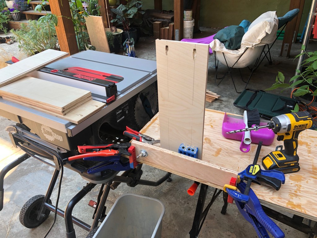
This looked terrible. For round 2, I tried using pocket holes to hold it together.

I built two drawers held together by pocket screws around the bottom (everything in the photo is 1/2" ply). I think these are strong, but I don’t like the Kreg pocket hole system. The drill guide itself was fine, but the ratcheting clamp system that is supposed to hold the guide against the wood constantly slipped. It was never tight, not once, so I created my own vise system. It worked, but it was a PITA.

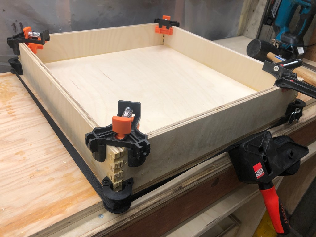
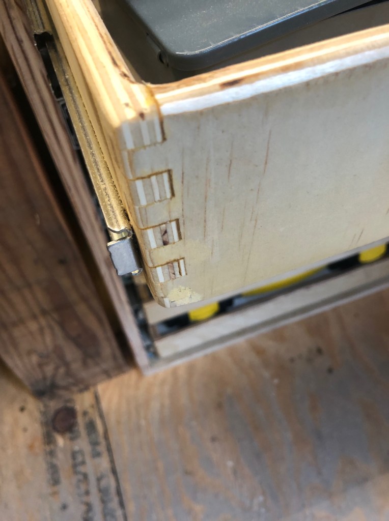
Next attempt: box joints. I found William Ng’s amazing system and followed it. I built the jig (twice, playing with it), and I made a couple of nice test pieces. Then I did four drawers. Findings: the jig tends to make a mess of the plywood, the dado blades tear out a lot on the back, even with tape or something else to try to reduce it, so many of the pins end up without veneer; any mistake in the jig setup amplifies through the cuts which can lead one set (say, the one with the pin on top) not to fit the other set (the one with the slot on top). I lost a few sets of sides + fronts this way, and it’s enormously frustrating. Also the amount of cutting is much larger than with other joints, the saw is very loud, and the dado creates a vast amount of sawdust. The pins didn’t fit together very well, so I ended up with a lot of wood filler in the joints. This is a very strong joint, and it’s cool looking, but it’s a lot of noisy, dusty work for an uncertain outcome.

Finally, I routed a dado slot 1/4" deep 1/4" from the bottom of the sides + front + back, and then slid a 1/4" piece of plywood into the slot for the drawer bottom. Glue everywhere, and spread with a brush. This was a good move, fitting the bottom like this helps the drawer stay square. The box joints make getting to square a little tricky. And the box joints make the final drawer dimensions a little bit of guesswork: how tightly will the joint parts fit together? How much space will the glue take up?

For the four narrower but taller drawers, I just used pocket holes from the sides into the front + back, and they worked ok. Not great, I have to say, because drilling the pocket holes was still a PITA. But with the dado slot for the 1/4" ply on the bottom, the drawers are square, and it was pretty easy to assemble and glue the drawers.

Shop dog is now 15 weeks and ~22 lbs

So I have a cabinet now — yay! And it really is a yay, notwithstanding the enormous effort for mediocre outcome. I’m still proud I did it, from never making a carcase or drawer, nor hanging one, to having a functional piece of furniture in about 3 weeks (including the week I was down with maybe-Covid).

The drawer slides from Lowes’s don’t suck, but they’re not fantastic. I had to fiddle with the drawers to get them to fit: some needed a very slight shave (I resawed the plywood sides on one drawer, took off 1/16"), some needed a shim (lesson learned #2: put the shim between the slide mount and the drawer, and put all the shims on the same side of the drawers so they vertically align). Even so, the drawers aren’t as smooth as I’d like.

For all the drawers, I flush trimmed all the corners with the router, then rounded over all the touch bits, then sanded a couple passes with 60, 150, 220. The fronts all got some shellac, and the right side drawers got stained before the shellac.

Last note: to install the drawer slides, I used plywood cut to the height inside the carcase I wanted the bottom of the slide. Then I clamped the plywood to the carcase and set the slide on top while I screwed it in. I played around a little with how the slide should attach to the drawer, but it’s a simpler bit of math than it seems. The keys are getting the slides equally spaced vertically on each side so left and right align; and getting the slides perpendicular to the carcase sides. The plywood is square so assures that the slides are parallel to the bottom of the carcase, and using the same plywood support on each side assures that the two sides are equally high. I was careful to cut the plywood an equal amount for each drawer, so I got equally-spaced drawers.

I often find myself trying to figure out how to bolt something into wood. Say I’m attaching the side of a wooden box, but I want to be able to remove it later. Ideally I’d have a threaded hole, but of course wood won’t hold a thread. I don’t want to use a wood screw because after I’ve taken the screw in and out a few times, the hole will be reamed and won’t hold.

I could use a threaded insert, but the smallest ones I can find are #8, and they require a pretty big hole. And of course I would have to remember to order them a week or so before I start building.

Here’s my newest idea. For a #6 bolt, I set up the drill press and used a forstner bit to drill a 3/8" hole about 3/16" deep, then a 11/16" center hole. I set the nut into the hole made by the forstner bit with a little Amazing Goop from my favorite hardware store. (everyone should have a hardware store they really like, I think)

I needed to clean the threads a little but it seems to work pretty well. The key is that the nut must stay in place when the bolt hits it. If the nut falls out into the inside of the box, it fails. I was able to break the adhesive by threading the bolt halfway into the bolt, then pushing the bolt out of the wood. I pushed hard enough to leave a dent in my thumb for a couple of minutes, and I think that’s probably strong enough. Notes: cyanoacrylate glue doesn’t really work at all; and gorilla epoxy is kind of a pain to set up but it sticks the nut onto the wood a little better than Amazing Goop.

Once the bolt is seated, all’s well — the bolt’s pressure will draw the nut into the board I’ve set it into. This is going to be a go-to solution for me, I think, but I might need to tune the adhesive a little bit.

One of the electronics maker’s "hello world" projects is converting an old desktop computer’s ATX power supply to a DC bench power supply. I’ve built 3 or 4 of these over the years, and I generally blow them up by shorting them when I’m testing a new circuit. They can take a little bit of abuse, but not very much. I’ve thought about lots of ways to create protection circuits to shut off if there’s too much current drawn (like in a short), but let’s be serious: I’m never going to build a really good power supply.

But I’ve kept trying, if only because good power supplies are $400+, and I’ve got a bunch of ATX stuff lying around. A few weeks ago, I decided to try again with parts I have on hand, including a breakout board that converts the ATX jacks into separate +5v, +3.3v, +12v, and -12v screw terminals. Each voltage has its own jack and on/off button, and the buttons drive relays so the power is isolated from the controls. The buttons light up when there’s power at that jack. Plus there’s a jack that can switch between 3.3, 5, and 12v, and it runs through an ina260 so I can monitor the true voltage and current. Nifty! I thought.

In the photo below, the power supply (the vertical plastic box) is connected to a constant load (I’ll write about this another time). What you need to know about a constant load is that I can set it to draw a fixed current, say 1000mA, no matter what the voltage is.

Here’s the thing: maybe the most important reason we build a constant load is to test power supplies. The idea is that if we tell a power supply to give us, say, 5v, it should give us 5v no matter how much current we try to draw (up to the supply’s capacity). This is what a good power supply would do, anyway. It turns out that ATX power supplies rather badly fail this requirement.

My constant current load runs the power it’s drawing through (yet another) ina260 board which is monitored by an arduino. I did this so that the constant current load can log the voltage and current (and some other stuff, like the temperature of the mosfet that’s burning off the power as heat); the log is written to the serial output through USB (you can see the USB glowing blue, I love cables that blink). From the data generated by the constant load’s cycling through a range of currents, I have created the graph below.

This is Not Good. We want the lines to be flat, that is, we want to see the same voltage at every current. These are not flat. For example, the 5v supply drops from 5.3v at no current to less than 4.5v at 3300mA. This power supply claims to be able to provide 10A at 5v, and nope, that’s just not true. While the proportional loss for 12v isn’t quite as bad, 3.3v is worse.

I think I need to stop messing around with these crappy ATX power supplies. I’ll just build a box with a bunch of jacks — and remember that the voltage is srsly unreliable.

I have a Siglent SPD1305X, and it’s great for one voltage, but I find myself needing several voltages at the same time. Furthermore, I sometimes need a negative voltage source. I guess I’ll start saving for a Siglent SPD3303. It can do all the power things.

A few weeks ago my house was burgled, and the thief stole most of my construction tools. I was devastated. However, my friends came together and created a fund that has enabled me not only to replace the stuff that was stolen — I’ve also been able to add a big new tool. Wow, my friends are great!

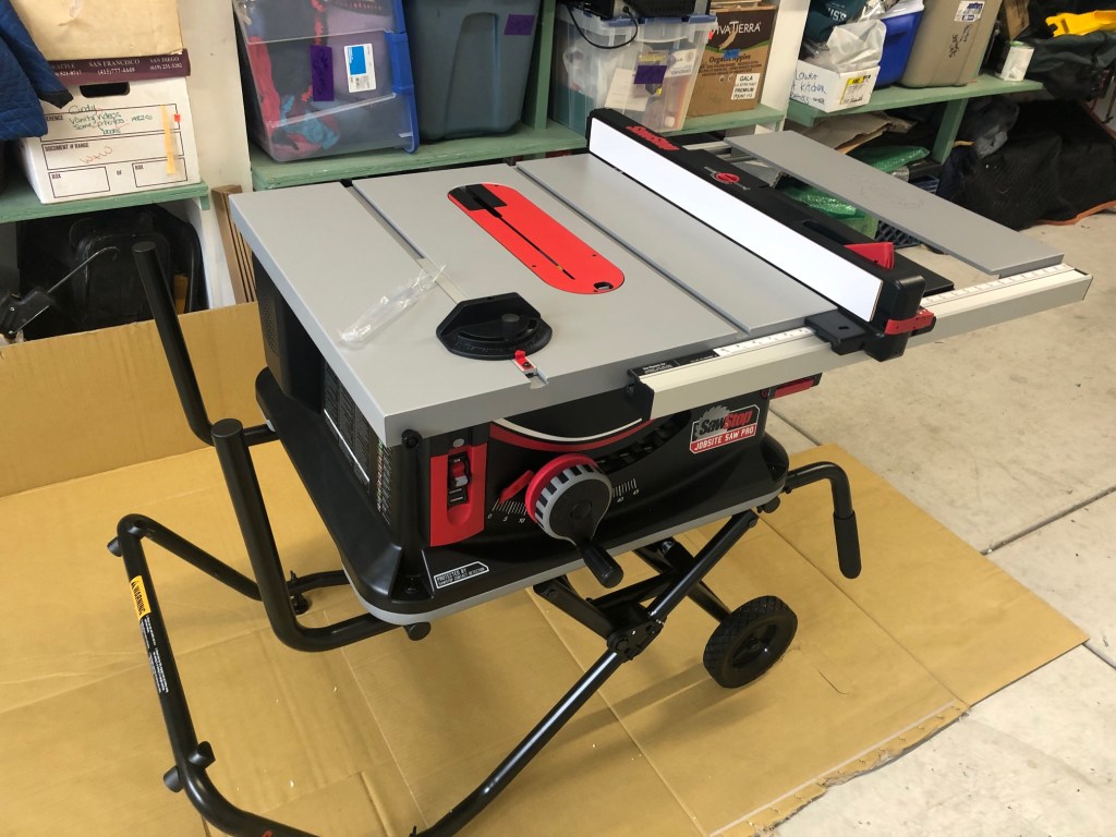
The tool I added is a SawStop Jobsite Table Saw. I got it for a lot of reasons; here are the top two. First, I want a table saw big enough to cut big plywood but small enough to store in the garage. This one is pretty easy to move around on its integrated hand truck.

Second, I wanted a saw with tech that recognizes a finger and refuses to cut it off. I’m very, very impressed by the testimonials from YouTubers I admire (like this one and this one) about how the SawStop actually stopped and they walked away from a situation where they could have been very seriously injured.

A table saw blade turns about 4000 rpm, the teeth are moving at about 200 feet per second, around 1365 mph. The teeth point toward the user (into the board you’re cutting), so the teeth can (and sometimes do) catch a finger and pull it into the blade. It happens so fast that you can be seriously injured multiple milliseconds before a signal can make its way to your brain. I decided to do the math.

A signal from hand to brain takes about 20-40 milliseconds (that’s just the transmission time, not considering any thought from the brain, let alone a reaction and retransmission). In half the shortest possible transmission time, 10ms, the teeth on the blade move about 2 feet. There are 50 teeth on my blade, so in 10ms, about 30 teeth pass through a given point. When I hit my hand slowly on just one tooth (like when I’m installing a blade), I get a good nick. 30 teeth (driven with effectively infinite power) could easily sever a finger in half the time it would take for the signal to reach my brain.

This model has a capacitive touch sensor in the blade. When it touches something conductive, like, say, a finger, it stops in <0.0004 seconds, which is less than the travel time for one blade tooth. The videos and testimonials are amazing. I love the one where they push a piece of steak into the blade and it stops with only a tiny nick. I bought this model bc I think it will reduce the chance of losing something important when I’m distracted for an instant.

However, I’m a little sad I can’t also have a hyper-precise Byrnes Mini Saw. It looks absolutely gorgeous. However, they’re not being made right now, and it would really be too small for anything other than building small enclosures for my electronics. But then again, most of what I want to do is build small enclosures. You can see the dilemma.

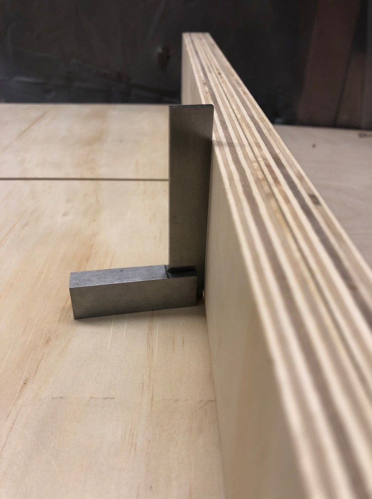
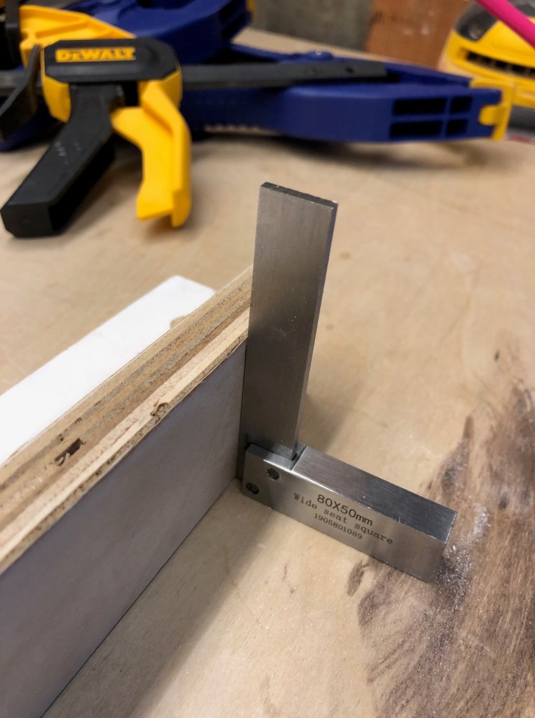
Availability won out, and I got the SawStop. Right away I noticed that making cuts with the fence isn’t precisely square. The key test is to cut a board on each side in turn, and then check square on the final cut. A simple cut using the saw’s fence is not all that close: look at all the light under the rule.

I decided to build a cross-cut sled, which seemed to me perhaps the most fundamental helper tool for a table saw. I followed the basic pattern described by Tamar at 3×3 Custom, though mine is somewhat simpler. There are tons of videos online about how to do this, so I’ll hit the highlights:

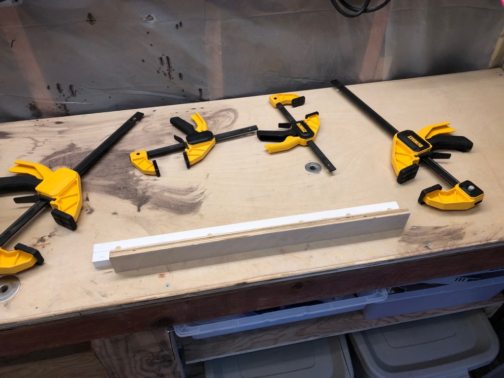
  • cut plywood for the back and front fence; I used two sheets of 1/2" glued together. I clamped them to a monster 1/4" thick chunk of aluminum L frame I have from an old project to make sure that as the glue dried, the fences stay as flat as possible. After they dried, I trimmed them so they are flush.
  • I cut runners out of a maple board; I used the sneak-up-on-the-cut method that Newbie Dan describes. I don’t know whether I cut the strips properly to account for how they shift with the weather. I used a Grr-Ripper to control the wood as I cut it. (btw I like the Grr-Ripper a lot).

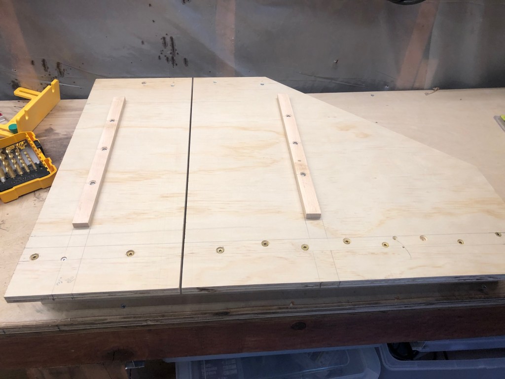
The image below is the bottom of the sled after I secured the back fence with a zillion screws.

The sled itself is about 18" deep by 24" wide, with a big chunk cut off the back left where I don’t think I need too much support and I can reduce weight (this idea comes from Tamar).

By far the most important part of the sled is getting the back fence perpendicular to the blade. There’s an amazing trick for this, invented by William Ng, called the "five-cut" method. The idea is to cut a board on each side in turn. The error (i.e., the amount the cut differs from perpendicular to the blade) compounds with each cut because the cut side becomes the base of the next cut. The amplification of the error makes it easier to measure and to correct.

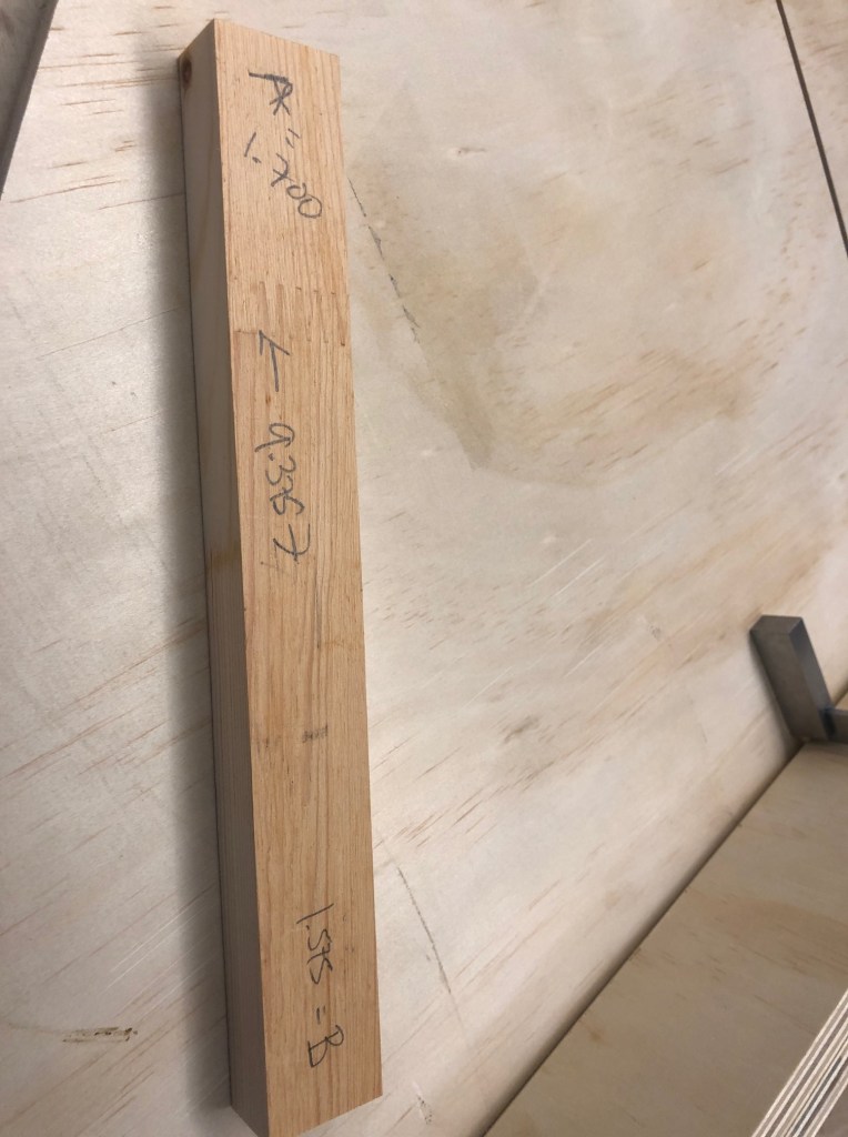
I’ll leave the explanation of the method to others – there are tons of great explanations of how to do the cuts and the calculations. Here’s my final cut with the associated measurements.

(note: the A measurement is 1.1700, and B is 1.1575; when. I wrote on the board, I omitted the ‘1’ in the tenths position, oops). From this, you can calculate that my sled’s error is ((A-B)/4)/len(test) = 0.00033 per inch. That is, cuts made with this sled will be off square about 3 ten-thousands of an inch over every inch of cut.

So if I cut a board 24" square, the diagonal in one direction would be around 0.02" different from the diagonal in the other direction. I can definitely live with that! Of course this sled is too small to cut 24" square, but you get the point.

This is a first attempt. The runners aren’t great, the fences should be 3/4" rather than 1/2", and the whole thing should be made of higher-quality plywood. But it’s a great "hello, world" with my new saw.

And it’s a great lesson that in woodworking (probably in other areas, too), the great tool only gets you part of the way. There’s some skill, sure, but also some technique (which isn’t quite the same as skill).

Finally, I’m really glad to have a way to cut seriously square. This is a great first post-burglary project. I’m deeply grateful to my friends.

PS: yes, we changed & upgraded all the locks, and we added cameras that save video to an online repository (the "cloud"), but crucially for me, the cameras do not connect to the police. And in the garage, the saw is chained to a bolt drilled & epoxied into the foundation. Of course we could be burgled again, but it’s going to be tougher for the next thief.

After many years, my 2012-era MacBookPro began rebooting so often that I could not continue. Furthermore it was often losing track of Arduinos plugged into the USB, and while that may have been an issue with the Arduino IDE, I was unable to fix it, and it was annoying.

Let’s take a minute to honor the MacBookPro. It’s been to Burning Man at every year since 2015, I’ve taken it to around 20 countries, I wrote an immense amount of code, email, and prose on it. It hasn’t been my primary work computer for at least 5 years, but it’s been in the lab, and it’s been the host for a stack of thunderbolt-connected RAID drives. It’s a very fine little beast, and I expect it will have a dignified retirement.

However, after the fifth reboot of the antique MacBookPro in a single day a couple weeks ago, I lost patience and bought a System76 Meerkat mini. I’ve been a happy manager of a System76 server for about five years (it’s been great except for a frequently-failing cooling system that I’ve replaced 4 or 5 times now), so I’m happy to do more business with these folks.

But while I waited for the new computer to be delivered, I managed to use a RaspberryPi 4 to program some Arduinos using vim, python, and platformio (platformio is amazeballs). I’d had a lot of trouble getting platformio running under MacOS, which is weird and surprising, but under rasbian-linux, it Just Worked. Using a RPi as if it was a real computer was great! It got me psyched for a new desktop linux machine.

I used desktop+laptop linux from about 1999-2007. I tried again in 2015, and it wasn’t successful. There are too many little connections that Apple makes completely transparent that I couldn’t get a linux box to do, even with a huge amount of fiddly work. However, I think that in the lab it should go better. Here I think around 95% of my work is in a browser and a terminal, and linux should do well.

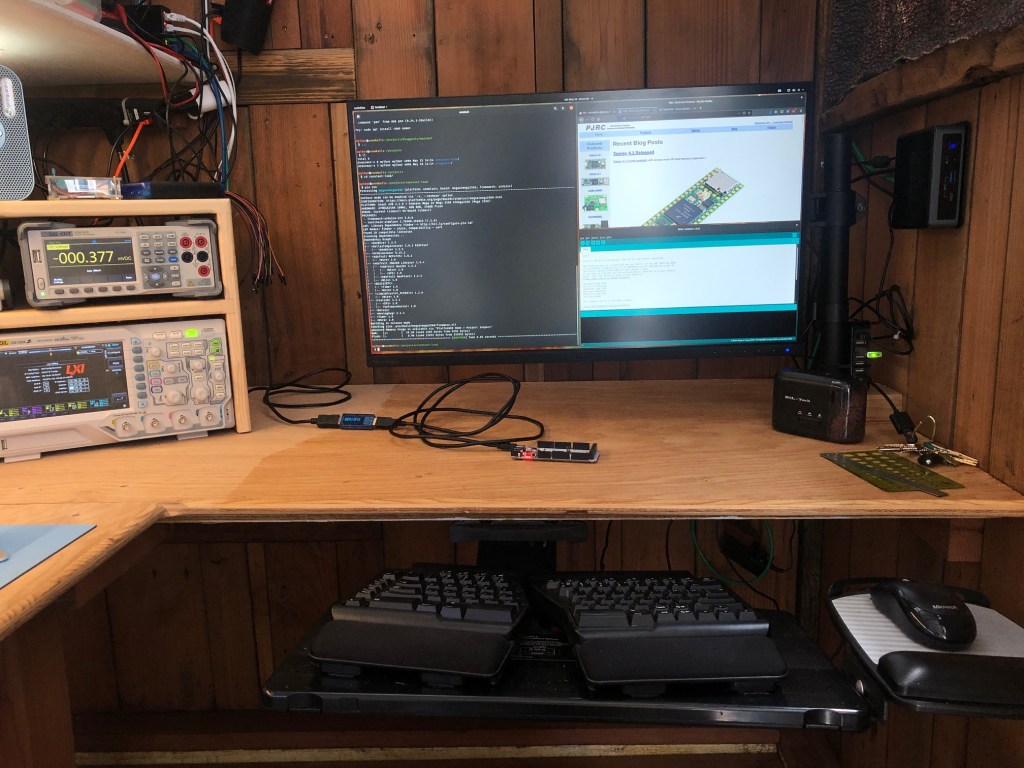
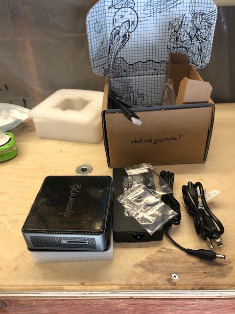
The Meerkat arrived yesterday, and it’s totes adorbs. In the photo above, it’s mounted on the wall on the right. The photo below shows the unboxing.

It’s just a box. Put video in with HDMI, attach a keyboard+mouse, add a network connection, and we’re off!

First, the Pop!OS is a terrific set of themes for gnome. It looks fantastic, and so far I’m really enjoying their version of tiling windows and workspaces. The hardware and the GUI tuning make the UI as responsive as anything I’ve ever used. The keybindings are all a little off from my MacOS muscle memory, but it’s close enough.

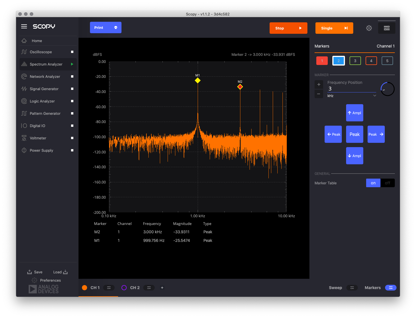
In about a half-hour, I had my key apps running: the Arduino IDE from the pop shop, Spotify from Ubuntu’s snap installation utility, and Scopy for the M2K multi-instrument in a flatpak.

It’s weird to have all these different package managers. There’s the "pop shop" and of course apt-get (because Pop is Ubuntu which is Debian), and snap and flatpack and the Adruino IDE’s library manager. I use anaconda python and I can add libraries with conda but also directly through python’s pip. For math, I use RStudio which leverages the Comprehensive R Archive Network, and the TinyTex package to write Rmarkdown and LaTeX. TinyTeX uses the tlmgr manager for LaTeX sty files. Platformio manages it’s own libraries for microcontroller hacking. Even my editor has it’s own package manager.

It’s going to be a headache to keep these straight, esp popshop-apt-snap-flatpak mix. I know that I’ve had issues keeping conda and pip straight, so this is going to be a little challenging. But for now, everything on this list is working (with one exception, see the next graf). And best of all, it all worked pretty much just by installing with the aforementioned package managers. I’m impressed.

There’s a confusing partial-overlap between the UI settings managed by gnome-tweaks and those in the Pop!OS settings app. For example, to turn on the unix-standard readline keybindings for within-text navigation, and to fiddle with gnome-menu-extensions I had to use gnome-tweaks. Then it didn’t work until gnome-shell was rebooted some arbitrary and large number of times. But it did start working! Maybe I’m missing something in the settings app. All this said, the GUIs for settings are miles ahead of last time I played with desktop linux.

So far, nearly everything has worked almost without having to google a weird error message. The piece that doesn’t work yet is Scopy+M2K. For some reason, Scopy doesn’t see the M2K on the USB connection. The kernel sees the M2K, which I can tell by dmesg. I’ll figure this out. edit: after adding the ADALM2000 udev rules and a bunch of reboots, it just started working. Well, ok, then.

My initial impression is that the Meerkat is fantastic. It’s tiny, reasonably cheap, powerful as all heck. The software System76 has prepared is really first-rate. Well done, FLOSS vendor! So far I’m a v happy customer.

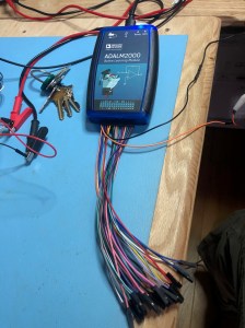
I got a ADALM2000 from digikey. It arrived quickly and without incident.

This device connects to a computer via USB and enables a lot of different measurements and kinds of signals. It doesn’t have a screen or controls, everything happens through the software on the laptop. I’ve been shopping for an arbitrary waveform generator, and this little box offers a pretty solid set of features for waveforms. In addition, it has a ton of other features, some of which I didn’t know about. It’s just arrived, so let’s take it for a spin.

First, I’m using this on MacOS 10.15.3, and the documentation says to install device drivers so the M2K is recognized by the operating system. The software they suggested gave errors when I tried to install it, but it turned out to be unnecessary anyway. I installed the control software, Scopy. And as all the best YouTubers say, let’s get started.

The device was incredibly easy to install and attach, so I’m going to skip that part. We forget about the stuff that Just Works. It’s a little annoying to have to figure out which of the many F dupont leads is the one I’m supposed to use for each feature, but I suspect I’ll just leave more useful leads in the appropriate connections.

The oscilloscope is the first tool. I attached it to my oscilloscope’s signal generator which emits a constant 1kHz square wave. And it looks exactly right. I didn’t play with the triggers, but the timebase and the volts/division were easy to set. Even easier was the autoset feature – it made a pretty good decision. I can imagine all the rest of the oscope stuff working pretty easily.

The network analyzer is another tool I’ve never used before. As far as I can make out, it’s basically a tool to test electronic filters. It generates a "stimulus" which it puts into the circuit. We measure the circuit at it’s input (going into the resistor) and its output (at the junction between the resistor and a capacitor). The resulting curve on the response channel shows how different frequencies are permitted or attenuated by the filter. The filter I put together (with a 1K resistor and a 2.2nF cap) starts attenuating at 1kHz and is strongest at 10MHz. Interesting.

I bought this thing for the waveform generation. I attached the W1 lead to my oscope’s lead, and GND to GND. I set it to a sine wave at 1kHz at 1v peak-to-peak, and it’s dead on. It’s also dead-on at 1MHz (shown), but it tops out at 30MHz, and at that speed, the signal is a tiny bit wobbly. To be fair, these are unshielded leads, and I think this speed is pushing my oscope’s ability to capture the signal reasonably, so I’m impressed.

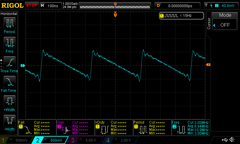
The square wave is a little less stable. At 10MHz it’s a wobbly mess. However, by 1MHz, it looks square and stable. Similarly the triangle was wobbly at 10MHz but looks great below around 4MHz. In the image below, the sawtooth at 3MHz is a little wobbly.

There are the usual waveforms (sine, square, triangle, sawtooth) and options to input user-generated waves or output from math functions. This is exactly what I wanted. Just this is enough to make me pretty happy with this device.

The logic analyzer might for me be this device’s killer app. This is for figuring out whatever is going on in digital signals. I want to know.

I’ve been playing with some APA102 LEDs (Adafruit calls these DotStars) and a Teensy4. I write into the LEDs using the FastLED library. The protocol that the software on the Teensy uses to shove bytes down the wire is called SPI.

The wires that go to the LED strand go through a chip called a 74HCT245. This chip shifts the voltage from a barely readable-400mV to a stable 0/5v LOW/HIGH pattern. I’ve been curious if anything else happens in this chip, like say, a bunch of noise.

The logic analyzer lets me read the signals as they go through the line. Even more cool, it freakin’ decodes the signals so I can see what’s going on. In th eimage below, channels DIO1 and DIO3 measure the clock signal. Whenever the clock rises, the LED chips read the signal (HIGH or LOW) on the data line (which is measured on DIO0 and DIO2). Signals DIO0 and DIO1 are measured coming out of the Teensy, while DIO2 and DIO3 are measured coming out of the 74HCT245. This enables me to compare the two to see if they differ.

All this is happening one million times per second. Wow. This is a great tool.

The pattern generator creates digital patterns like the ones that the logic analyzer reads. In some sense, a signal generator is to an oscilloscope as a pattern generator is to a logic analyzer.

The digital IO is pretty easy to figure out: you can put a 5v signal on a channel, or measure one. Since there are 16 channels, that makes this a pretty convenient breadboard helper.

The voltmeter is interesting. First off, it’s helpful to have two channels. But be clear: this is a "voltmeter" in a sense similar to Adafruit’s fantastic ina260 measurement board. It’s delicate, will fry from reverse voltage, and has a very limited range. And it’s not all that accurate.

I connected the Adafruit LM4040 voltage reference board. I used the M2K voltmeter first on the high reference voltage. It should be 4.096v, but my Siglent SDM3055 says 4.103v (the Siglent is still within its calibration period). Meanwhile, the M2K thinks the voltage is somewhere between 4.055 and 4.162, a range of over 100mV. In this case, the truth does indeed lie in the middle, but that’s a wide range. Checking the low reference (nominally 2.048v), I see 2.0505v on the Siglent, but 2.007-2.078v on the M2K; it’s in range but has trouble figuring out where. I measured the voltage coming out of the power supply and found it to be a little high (5.044-5.142v): my antique but very reliable Fluke 45 says 5.005v.

The last tool on the M2K is a low-current power supply (good for up to 50mA). To use this, you have to attach a second USB cable. Ok. I measured both the positive and negative supplies over a 390K resistor. The power supply says it’s delivering 2.999v and the Siglent reports 2.999v; on the negative side, similarly the reported VDC is within 1 mV of what I’m measuring. Nice! It’s really helpful to have a negative power supply to prototype op-amps. For very low current applications, this is a great addition. I wonder if it has a fuse? Or short protection? (It’s an open source tool, so I could look up the schematics) I really needed another power supply, so this is a great addition to my bench.

Cons

What don’t I like? Well, the docs are horrible. There are basically no wiring examples (except for the network analyzer). Much of the documentation just narrates what I can see in the software without telling me how to set it up or why I should use it.

Possibly the more meaningful documentation is in what looks like a very impressive set of lab exercises that are a companion for the M2K. I’m looking forward to reading through it all.

The device feels cheap and crappy. The leads don’t fit smoothly into the housing. The dupont leads are definitely going to break or bend or otherwise become trash pretty quickly. I’m amazed that they didn’t print a sticker for the pinouts like their really useful internals diagram. I’ll be adding that.

And as I’ve mentioned, the voltmeter isn’t very good.

Pros

These minor issues aside, the M2K is a fantastic tool for my bench. The Scopy software is really good. The device has done exactly what I expected, and the software was a big help. I love that it’s open source hardware. I’m excited to log more stuff which this will make really easy. The ADALM2K + Scopy will complement my other bench instruments (power supply, multimeters, oscilloscope) by adding a few more channels and slightly easier logging. Adding the analyzers, generators, and digital IO, and we have a great package. I look forward to a lot more fun with this thing.

So I’ve wanted to do a project that accomplished several goals. First, I need more blinky stuff in my lab. What good is a lab if there aren’t bunsen burners bubbling, inscrutable machines whirring, and, best of all, little lights blinking?

Second, I wanted to learn how to use basic integrated circuits, and one of the most useful and classic is the 74HC595. This chip is a shift register which means that it takes a serial input and writes it to 8 parallel outputs. You can chain several of these together, and so still using only 3 wires from a microcontroller (like an Arduino, which is what I’m using here), drive 24 signals. Here’s what it looks like on an oscilloscope:

These are the signals from the Arduino to the 74HC595. Let’s read the oscilloscope from the bottom up. The purple line is the latch. When this signal is pulled LOW, the 74HC595 listens for data. The blue line in the middle is the clock: when it rises from LOW to HIGH, the 74HC595 checks the input signal. So when the blue line rises on the left, the 74HC595 checks the signal measured by the yellow line (called serial), and sees that it’s HIGH. That’s a 1. The blue line cycles down, then back up, and the 74HC595 reads again: another 1. And so forth, in my case, for 24 bits.

When the latch is set, the bits are pushed into the chip. Each 74HC595 only remembers 8 bits, so if there are more, it pushes the rest out on pin 9, called $Q_H’$, which is read by the next chip (if there is one). I chained 3 chips together, thus 24 bits in each latch-unlatch cycle. This all happens in about 450 microseconds, which is pretty fast for people, but pretty slow for electronics (this means we could only do about 2000 of these cycles per second). This chip was invented in the early 1980s, though there were very similar versions long before this time. I think it’s amazing to use something from that era for a useful purpose now.

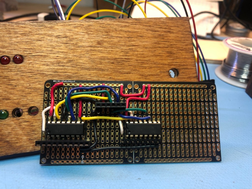
To build this, I need a way to take the 3 signals from the Arduino to the 3 chips. After a lot of prototyping, I wired the chips together with a header for the Arduino (in the middle of the wires) and with headers for the LEDs (below the chips) together on this great strip board. This photo is when two of the chips are soldered, waiting for the third.

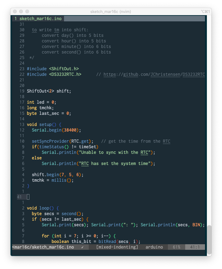
Of course I need a clock. I used a cheap DS3232RT with this library. We’re going to need to introspect a little bit, so I added a somewhat clunky but entirely functional 20×4 LCD screen that speaks I2c. And I added a giant, blinking arcade button.

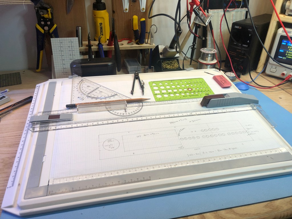
I spent a long time figuring out the layout. I should have done this with some kind of modeling software (which I really need to learn so I can do CNC milling and 3d printing), but I just Old Skool drafted it.

I put the enclosure together in a bit of 1/4" hobby plywood from the hardware store, stained to look like it isn’t totally crappy. One of the pieces that took me longest to figure out is how to cut a hole out of the middle of the board, and make it square and parallel. This wasn’t easy because I’m a seriously crappy craftsman.

The basic idea is to drill 3/8" holes in the corners, then use a jigsaw to cut between the holes. I built three different jigs to try to get cuts straight and square. Nope, then nope, then nopest. Finally I saw a YouTube video (which I’ve now lost) that said, like everybody just knows this, to put the panel on a vise, then file the sides flat and square.

The key I discovered is to cut rough using the technique above, but then put aluminum L stock on the vise jaws, and align the panel with the L stock up just barely under the mark for the edge of the hole. Then file the wood flat to the L stock, and the filed line with follow the line of the L stock. If I’ve set up the L stock up correctly, we’ll get a good square. It worked! The hole is square and parallel to the board used for the front panel. And now I have a set of Very Serious Nicholson files (I love good tools so much). The LCD dropped nicely into the hole, and I secured it there with some sugru and a few tiny screws. The LCD shows the decimal and binary values for each of the four variables shown by the LEDs as a kind of cheat sheet.

I mounted the LEDs into the front panel with hot glue. Note to self: big LEDs fit perfectly in a hole 13/64", while the little LEDs slot into a 1/8" hole.

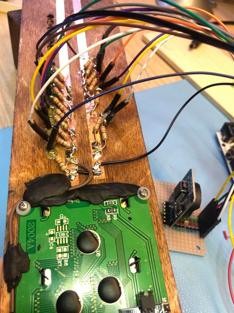
I put a 330Ω resistor on each LED’s cathode and then soldered it to strips of copper tape I affixed to the back of the front panel as a ground bus. I put pre-crimped leads from Pololu on the anodes. I organized the wires in connector housings that I could attach to the PCBs. I made 3 bundles of 8 wires (one for each 74HC595) plus a ground wire.

There are 2 boards: one for a I2c bus for the clock and the LCD, and a pullup resistor for the button; and one for the 74HC595s.

The front panel is connected to the back by 1/4" bolts through little blocks I cut out of 2x4s. A bolt through the back panel, the block, and the front panel with an acorn nut holds it all together. Perhaps I’ll cut acrylic sheet for the currently-open sides.

It works! I’ll post the code below until such time as I get a minor GitHub repo set up. I’m grateful to Slobberchops for his help: I’ve never sliced bytes and twiddled bits before (I live a little higher in the stack), and I’m delighted to have done it with his help. I hope to make this compile with arduino Makefile. That’s the next rev, and I’ll update this post with a GitHub link when I get this a little cleaner.

/*    Author: wylbur  https://wylbursinnergeek.net 
 *    
 *    Date: 2020-04-23
 *    License: GPL v2+
 *   
 *    building on the shoulders of others. Thanks. 
 *  
*/

#include <Wire.h>
#include <LiquidCrystal_PCF8574.h>  // https://github.com/mathertel/LiquidCrystal_PCF8574
#include <DS3232RTC.h>              // https://github.com/JChristensen/DS3232RTC
#include <FastLED.h>

#define DEBUG 1
#ifdef DEBUG
  #define DEBUG_PRINT(x) Serial.print(x)
  #define DEBUG_PRINTLN(x) Serial.println(x)
#else
  #define DEBUG_PRINT(x)
  #define DEBUG_PRINTLN(x)
#endif 


const int ledPin = 3; 
const int buttonPin = 2; 
const int dataPin = 7;
const int latchPin = 5; 
const int clockPin = 6; 

LiquidCrystal_PCF8574 lcd(0x27); // set the LCD address to 0x27 for a 16 chars and 2 line display

// https://stackoverflow.com/questions/111928/is-there-a-printf-converter-to-print-in-binary-format
// part 1
const char *bit_rep[16] = {
    [ 0] = "0000", [ 1] = "0001", [ 2] = "0010", [ 3] = "0011",
    [ 4] = "0100", [ 5] = "0101", [ 6] = "0110", [ 7] = "0111",
    [ 8] = "1000", [ 9] = "1001", [10] = "1010", [11] = "1011",
    [12] = "1100", [13] = "1101", [14] = "1110", [15] = "1111",
};


boolean fadeDirection = 1;
byte fadeValue = 0; 

volatile boolean displayMode = 0; 
boolean lastDisplay = 0; 
volatile unsigned long last_button = 0;
int last_second = -1; 
unsigned long last_us = -1; 

char line1[21] = ""; 
char line2[21] = ""; 
char line3[21] = ""; 
char line4[21] = ""; 
byte r1 = 0; 
byte r2 = 0; 
byte r3 = 0;
byte days;
byte hours;
byte mins; 
byte secs; 
byte dd;  // 5 bits
byte hh;  // 5 bits
byte mm;  // 6 bits
byte ss;  // 6 bits


void setup() {
  Serial.begin(9600);
  delay(250); 
  Wire.begin();

  attachInterrupt(digitalPinToInterrupt(buttonPin), modeSwitch, FALLING); 

  pinMode(latchPin, OUTPUT); 
  pinMode(clockPin, OUTPUT); 
  pinMode(dataPin, OUTPUT); 
  
  DEBUG_PRINT("LCD...");
  printf_init(lcd); 
  Wire.beginTransmission(0x27);
  int error = Wire.endTransmission();
  if (error == 0) {
    DEBUG_PRINTLN(": LCD found.");
    lcd.begin(20, 4); // initialize the lcd
    lcd.setBacklight(255);
    lcd.home();
    lcd.clear();
    lcd.setCursor(0, 0);
    lcd.print("Hello binclock");
    // lcd.setCursor(0, 1);l
    // lcd.printf("hello world %d\n", 42); 
    delay(2000); 
  } else {
    DEBUG_PRINTLN("LCD not found."); 
  }
  setSyncProvider(RTC.get);   // the function to get the time from the RTC

  #ifdef DEBUG
  if(timeStatus() != timeSet)
    Serial.println("Unable to sync with the RTC");
  else
    Serial.println("RTC has set the system time"); 
  #endif 
    
  lcd.clear(); lcd.noDisplay(); lcd.setBacklight(0);
} 


#ifdef DEBUG
unsigned long loopctr = 0; 
#endif

void loop() {
    EVERY_N_MILLISECONDS(25) {
      if (displayMode == 0) {    
          if (fadeDirection == 1) { 
            fadeValue += 3; 
          } else {
            fadeValue -= 2; 
          }        
          if (fadeValue >= 150) {
            fadeDirection = 0; 
          } else if (fadeValue <= 0) {
            fadeDirection = 1;
          } 
      } else {
          fadeValue = 0;
      }
      analogWrite(ledPin, fadeValue); 
    }

    #ifdef DEBUG_A
    Serial.print(fadeValue); Serial.print("  "); 
    Serial.print(fadeDirection); Serial.print("  "); 
    Serial.print(displayMode); Serial.print("  "); 
    Serial.print(millis()); Serial.print("  "); Serial.println(last_button); 
    #endif 
   
    EVERY_N_MILLISECONDS(50) {
      byte secs = second();
      if (secs != last_second | displayMode != lastDisplay) {
        time2bytes(); 
        bytes2serial(); 
        update_lcd(); 
        last_second = secs; 
      }
    } 

    #ifdef DEBUG
    EVERY_N_MILLISECONDS(1000) {
      Serial.print(fadeDirection); Serial.print("  "); 
      unsigned long us_elapsed = micros() - last_us;
      Serial.print("us_elapsed="); Serial.print(us_elapsed); 
      Serial.print("; loops in elapsed="); Serial.print(loopctr); 
      float loops_per_ms = loopctr/(us_elapsed/1000); 
      Serial.print("; loops_per_ms="); Serial.println(loops_per_ms); 
      last_us = micros();
      loopctr = 0; 
    }
    loopctr++; 
    #endif
    
} 


void bytes2serial() {
  // push r1,r2,r3 to serial.
  digitalWrite(latchPin, LOW); 
  shiftOut(dataPin, clockPin, LSBFIRST, r3); 
  shiftOut(dataPin, clockPin, LSBFIRST, r2); 
  shiftOut(dataPin, clockPin, LSBFIRST, r1); 
  digitalWrite(latchPin, HIGH); 
}


void modeSwitch() {
  // it's a very noisy button
  if (millis() > last_button + 300) {
    displayMode = !displayMode; 
    last_button = millis(); 
  } 
}


void time2bytes() {
   days = day();
   hours = hour();
   mins = minute(); 
   secs = second(); 
   dd = days & 0x1F;  // 5 bits
   hh = hours & 0x1F;  // 5 bits
   mm = mins & 0x3F;  // 6 bits
   ss = secs & 0x3F;  // 6 bits

   r1 = (dd << 1) & 0xFF; // r1 has the rightmost 7 bits of dd (first two are 00)
   r1 |= (hh >> 4);       // hh is only 5 bits, so right shft 4 puts hh's first bit at end of r1
   r1 |= 0x80;           // to set only first bit
   /* 
   r1 |= 0xC0;  // to set both first bits on
   r1 |= 0x40;  // to set only second bit
   */ 
   
   r2 = (hh << 4) & 0xFF; // hh is 5 bits, so left shift 4 leaves bits4-7 at left of r2
   r2 |= (mm >> 2);       // getting the left 4 bits of mm (first two are 00)
   r3 = (mm << 6) & 0xFF; // rightmost 2 bits of mm
   r3 |= ss;              // ss is 6 bits wide and all go here
}

void update_lcd() {
   if (displayMode == 1) {
      sprintf(line1, "  dd: %02d  %s%s", days, bit_rep[dd >> 4], bit_rep[dd & 0x0F]); 
      sprintf(line2, "  hh: %02d  %s%s", hours, bit_rep[hh >> 4], bit_rep[hh & 0x0F]); 
      sprintf(line3, "  mm: %02d  %s%s", mins, bit_rep[mm >> 4], bit_rep[mm & 0x0F]); 
      sprintf(line4, "  ss: %02d  %s%s", secs, bit_rep[ss >> 4], bit_rep[ss & 0x0F]); 
      
      if (lastDisplay != 1) {
         lcd.clear(); lcd.display();  lcd.setBacklight(255);
         lastDisplay = displayMode; 
      }
      lcd.setCursor(0, 0);   lcd.print(line1); 
      lcd.setCursor(0, 1);   lcd.print(line2);  
      lcd.setCursor(0, 2);   lcd.print(line3); 
      lcd.setCursor(0, 3);   lcd.print(line4); 
     
    } else {
       if (lastDisplay != 0) {
           lcd.noDisplay(); lcd.setBacklight(0);
          lastDisplay = displayMode; 
       }
    }
}


// done. 

I suck at craft. I can’t cut straight with a razor or a saw, and get a cut square? Forgetaboutit. I’ve got a Kreg square cut, and that helps a lot. It works a treat when I need to cut a 2-by with a substantial length on each side, or for a short plywood cut. However, it’s useless for small pieces, and it’s often cumbersome because you need to hold it carefully with the left hand while managing the saw with the right. Awkward can be scary when a circular saw is involved.

Crucially, I don’t have a table saw. Ok, I do have a teensy-tiny NovelLife Mini Hobby Saw, and it’s really great. I’ve managed to cut soft wood up to 1/2" and plywood up to 5/8", but very very slowly. It chokes a lot, and the table is only 9" deep. It’s a great tool, and I’ve learned a ton using it, but it’s usable only for the smallest stuff. I’m going to burn it up with overuse in the not too distant future, I suspect. All to say that to cut real lumber, I’m pretty much limited to my circular saw.

After much review on YouTube, I decided to make a crosscut jig. The idea is that the circular saw sits in metal tracks which make sure it cuts straight. Then mount a board square to the tracks. Wood to be cut goes against the square board, and even I should be able to get a square cut. Here we go.

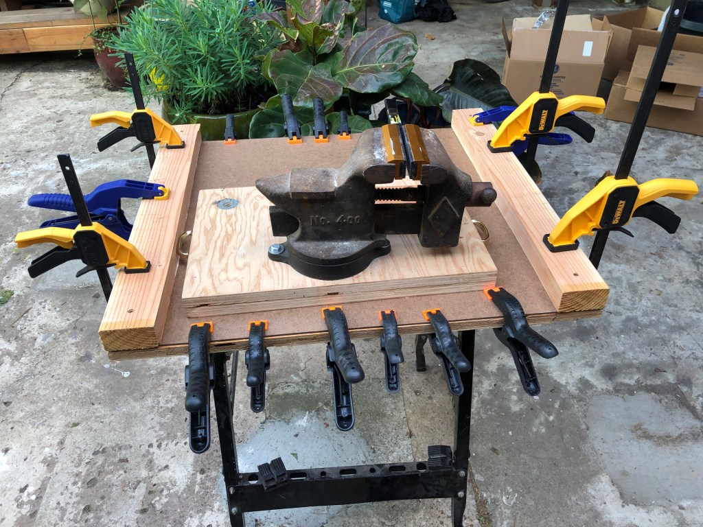
First thing is to build a table for it. I used a scrap of 5/8" plywood onto which I glued a sheet of hardboard. On top of that I glued and screwed 2x4s to hold everything together. In the photo, I’m waiting for all the glue to set.

Then I need rails. I had some 1/2" steel L rods from another project (that totally didn’t work out), so I cut them with a dremel (dramatic sparks!) and drilled holes to mount them onto the 2x4s.

I mounted the rails to the 2x4s and found that the clearance underneath them was a little too tight to cut 2-by lumber. So I pulled the rails off and added a 1/4" layer of plywood between the rails and the 2x4s.

Then I found that I really need the whole run of the rails, and it wasn’t quite long enough. The screws securing the rails were in the way of the saw’s bed. I pulled the screws out again, countersunk them with a 3/8" carbide bit (man, carbide bits just eat steel, pretty cool). Then I reset the rails, adding wood glue to the screws so they’ll adhere to the somewhat-stripped holes. Now the saw bed can run smoothly over the screws.

After I got the fence in place, I ran the saw back and forth, scoring the hardboard. I found that the saw can’t quite go to it’s maximum depth because the motor housing bumps into the rail, so I lose the last 1/4" or so of the saw’s possible depth. Ideally the rails would be 3/8", not 1/2", but, well, I had the 1/2" steel, so there we are. The saw cuts into the hardboard about 1/16", so it’s just barely enough to cut a board cleanly.

Next I need a fence. After several fails, I used a poplar 1×2, and glued a piece of finished 1/2" plywood onto it. The plywood will be the fence, so it needs to be both flat and square to the vertical. I drilled and countersunk pilot holes in the poplar to affix it to the table.

Finally I squared the fence to the cuts previously I made in the hardboard. I glued it and then set it with a bunch of screws, very carefully checking the square many times.

And it works! Yay! A little less craft-personship will be needed from here on. The rails need to be rubbed down with steel wool and then oiled, but that’s just maintenance.

I recently read Four Favorite Tools, a collection of essays from BoingBoing. I liked the style and the idea, so I thought I’d write about my four favorite tools.

Arduino hacking in NeoVim

There’s no competition: my favorite and most-used tool is NeoVim. This is a text editor, mostly for programming, but I use it for email and documents as well.

I write inside a unix terminal. People who are used to GUIs find the terminal clunky, but once you become accustomed to it, you’ll find it’s far and away the most efficient way to interact with a computer. By "efficient," I mean I can do the maximum amount of changing with the fewest keystrokes and arm movements. I can (and often do) wax a bit lyrical about vim and it’s many, many variants, but vim is worth it.

Note: I’m 30K words into a book written using NeoVim and markdown — and I’m writing this blogpost using a WordPress Markdown block — and I’ve found that Markdown is a pretty good basis for a long-ish book. The terminal+(Neo)Vim workflow lends itself naturally to keeping the book in version control in my GitHub account.

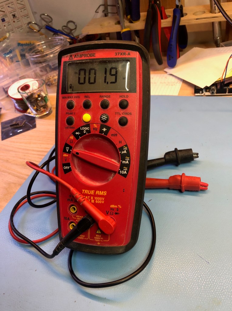
My 10-year-old Amprobe 37XR-A multimeter was the first tool I bought a second time. Before then I had a really cheap multimeter, I think the bottom-of-the-line that Adafruit offered. I bought the Amprobe at Fry’s because an old engineer recommended the brand to me. It’s a beast. I measure resistance, continuity, DC volts, and capacitance all the time (and DC current occasionally). This one has been to Burning Man 8 times, I just wash it with a little vinegar, soap and water in the sink when I get home. Really. It’s incredibly rugged, turns itself off automatically, and is accurate enough. I’ve got other multimeters now, and they’re much faster, more accurate, and have various cool features. This guy is the one I’m taking whenever I leave the lab. It’s been with me as I learned to be a maker, and I really like it.

Ratcheting wire strippers were truly one of the pieces that got me making. I couldn’t figure out how to strip wires without destroying strands, and the frustration built over several months until I got my first pair of these. I’ve got a few, various brands, and they’ve all been terrific. They work across a really wide range of wire gauges and insulation thicknesses. Nice.
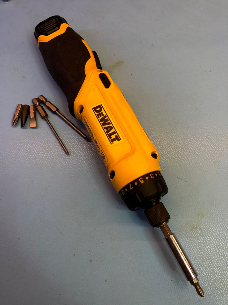
The DeWalt DCF680 is a magical tool. It’s motion-activated. The idea is that you align the tool to the screw or bolt you intend to turn, push and hold the black button, then with a flick of the wrist in either a clockwise or counter-clockwise direction, it turns. You control the speed of the tool with the strength of the flick.

After I used it for about 10 minutes, I found it incredibly intuitive. There are a variety of other power screwdrivers like this, notably the tiny motion control screwdriver Adafruit sells. I have a tiny one, and it’s nice, but the cheaper and vastly more powerful DeWalt is also subtler: I find that I can control the speed of the DeWalt with a lot of precision. Furthermore, the clutch on the DeWalt lets me set and then screw something until the clutch slips, no thinking and no stripping. Great stuff.

I have a bunch of other tools I’m really, really enjoying right now. Some are new, like the Siglent SPD1305x power supply makes controlling voltage and current so easy that it greatly reduces the chance I’ll blow something up with a short or reversed polarity. Or the soon-to-be-discontinued Rigol 1054Z which I’m slowly learning to use. Others I’ve used for decades, like the unix shell environment and tools. I’ll close with two slides from a talk I gave at the Linux Foundation a few years ago. I love tools.

What are your favorite tools?

(Updated with info on the Siglent)

A voltnut, or "metrology enthusiast" as our Brit and DownUnder friends say, is a person who gets really excited about knowing to many decimal places how much voltage and current is running through our little devices. I don’t really need all that, but when I’m playing with digital-to-analog conversion, I do need to know pretty accurately what the real analog voltage is.

I’d like to know to the millivolt, which at 5v means 0.02% accuracy, or "4 1/2 digits," in metrology-speak. Turns out that’s about five times more accurate than anything I have now.

This Fluke was built while I was in college.

I’ve connected the reference to all threefour of my measurement devices. First I have an ancient but wonderful Fluke 45 multimeter which claims precision to a tenth of a millivolt at the medium reading speed at 3v, or 0.02% (I can’t quite tell from their table). It has a calibration seal dated in December, 2000.

The newest toy on my bench is a Siglent SDM3055 multimeter. I won’t say more about it because mjlorton at YouTube has done a great review. The calibration cert on mine is good thru May 2020.

The Siglent multimeter is gorgeous

Next is my 10-year-old Amprobe 37XR-A, a beefy tool for serious electricians. This beast has been to Burning Man about 8 or so times, but it cleans up nicely for lab work.

Finally I’m using Adafruit’s ina260 voltage and current sensor which they report as "better than 1% accuracy."

In this test, I’m using Adafruit’s Precision LM4040 Voltage Reference Breakout. I give it about 5v, and it puts out 2.048v or 4.096v at 0.1% accuracy. That means +/- about 2mV and 4mV at the two output voltages, respectively. Setup in the pic below.

Not to put too fine a point on it, I’d like to know which of these devices is the most accurate. Alas, this test doesn’t really tell me. The results are in the table below.

device 2.048v 4.096v
Siglent SDM3055 2.0503 4.1032
Fluke45 2.0506 4.1036
Amprobe 37XR-A 2.047 4.098
ina260 breakout 2.052 4.103

The good news is (i) the calibrated Siglent and the Fluke are indistinguishable at 4.096v, and nearly so at the 2.048v reference (I believe the Siglent). They vary by less than half a millivolt here and in other tests. (ii) The Amprobe and the ina260 are within their tolerances at the 2.048v level, and the Amprobe is still within reference at 4.096.

The ina260 is within it’s stated 1% tolerance, indeed, it’s nearly as good as the other two with better tolerances. This said, it is not a voltmeter: it’s a very delicate IC on a breakout board. Reverse the polarity and you’ll fry the IC, and you can fry an upstream microcontroller’s I2C bus connected to the ina260 board. How do I know this? you wonder.

All this said, I can’t tell from this test which is the most accurate because most of the variation is within the variation on the LM4040. I also bought a AD584 reference, but it produced arbitrary values and seems to be defective.

Three action items emerge: (1) replace the AD584; (2) get the Fluke calibrated. And (3) indulge in a fancy new DMM, which I did. It’s great.