When you wire a button or a switch into a digital circuit, it might seem as though when the button is pushed, a circuit is closed, and there’s a digital HIGH or 1 available.
It’s not that straightforward, unfortunately. At the microscopic scale, the switch has tiny burrs that connect and disconnect several (or hundreds) times before it settles closed so that current can flow. This is called “bouncing,” and it’s the topic of many really great videos and blogposts. I even wrote one a few years ago, but now I have an oscilloscope so I can dig in a lot more deeply.
Mostly people handle it in software: if you see a button press, ignore everything for (about) the next 100ms, so you only count one press. A similar technique is to poll the button frequently, watching for a series of HIGH values, then counting only once it’s HIGH for a long enough period.
I am going to follow this video and report my findings (also a nice diagram and roundup of simple software techniques in this post). Here’s a picture of what button bouncing looks like.
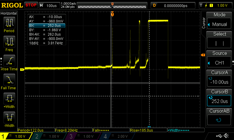
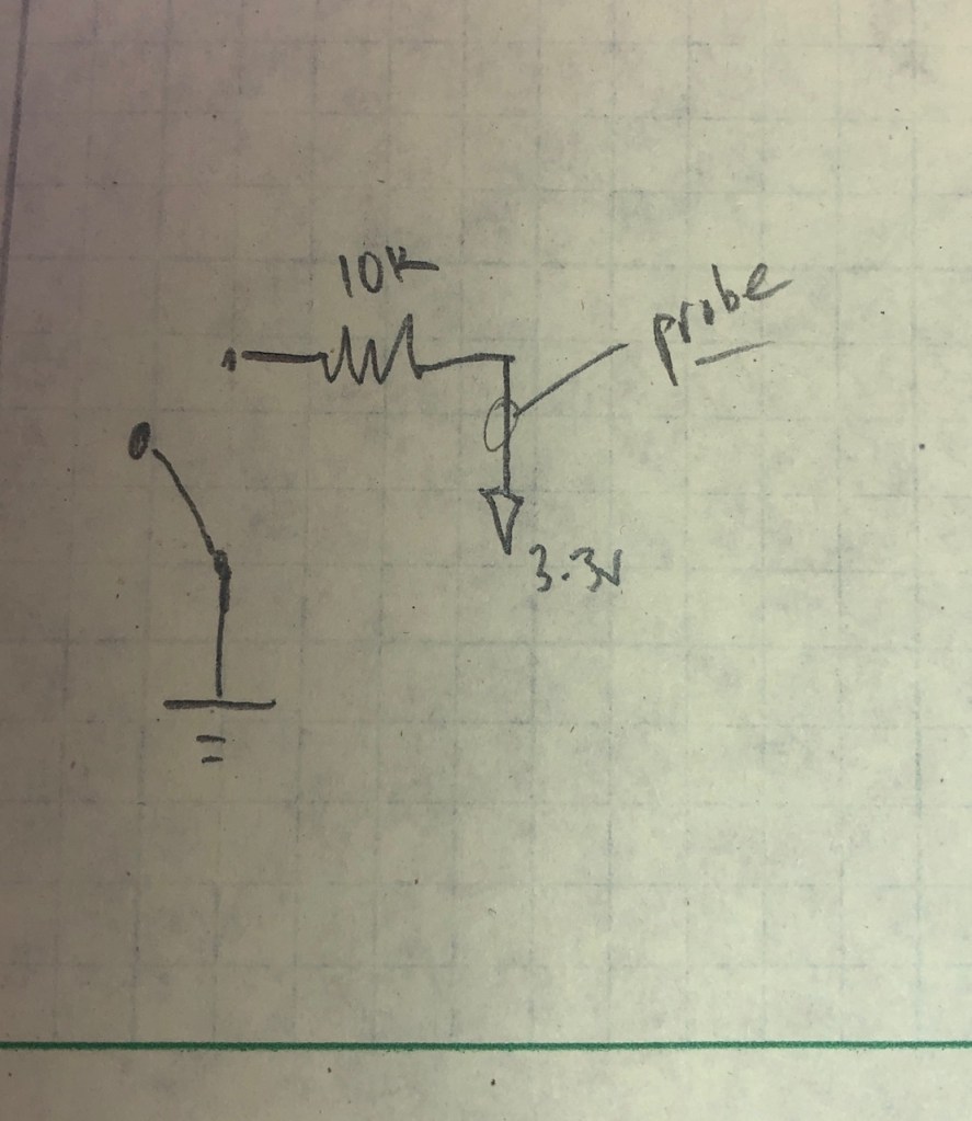
The button is wired on one leg to ground, and on the other leg, through a 10K resistor which connects to 3.3v. The probe is attached to the 3.3v side of the resistor. When I push the button, there’s an initial jump to 3.3 that lasts only about 120 nanoseconds (the solid white vertical line marks when I pushed, and I zoomed in to measure the time of the first bounce). After about 100μs (note that microsecond is abbreviated μs), the contact gets a little closer, and the jumps upward become more insistent. At about 240μs after I pushed the button, the button settles at a HIGH signal (note the dashed vertical line when this happens). I released the button only another 100μs later, and it dropped nicely to LOW (note that there’s not usually much bouncing when a switch opens because all the little rough bits are pulled apart more quickly than when they are closing).
The Teensy 4.0 I’m using here runs at 600MHz, about 6 cycles/μs. So there are more than 1500 cycles during the 262μs this button is bouncing. It’s easily capable of counting the 8-10 bounces above 1.8v (where it counts HIGH). That creates a mess when you’re trying to count button pushes.
For my test, I’m doing 2 separate things to the signal. First, I smooth the bouncing using a resistor-capacitor (RC) circuit. I can’t explain RC circuits, that’s a bit above my skills so far, but I recommend the Art of Electronics Lab Course, chapter 2. I’m digging through it now.
When the switch closes, the capacitor discharges according to the time constant, τ = R x C. The idea is that it takes about 5τ for the RC circuit to charge or discharge. The charging is exponential, not linear, and there’s a great tutorial about it here but alas, the graphics seem to be missing.

My graphics aren’t great, but here they are. R1 is the pullup resistor, and it’s 2K. The RC circuit starts with R2 at 680Ω and the capacitor is 1μF. That means that τ = 6.8e-4 secs, so it charges or discharges in 5τ = 3.4ms.
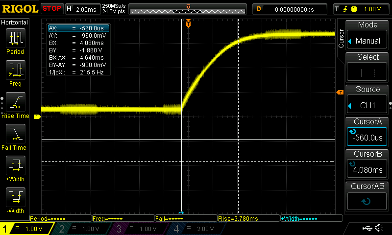
This is what happens when I press the button and measure the signal in parallel with the RC (before IC1 in the schematic above). Note that the two vertical lines mark the beginning and end of the capacitor’s discharge. BX-AX is about 4.6ms, which is pretty close to the theoretical 5τ = 3.4ms. I’m happy when my experiments match theory.
The point of this is to get a digital signal to the microprocessor, but the RC signal isn’t really square, it’s curved which forces the microprocessor to decide when the signal is HIGH. The Teensy can do that, of course, but once we start building this circuit, shouldn’t we get a square signal out of it?
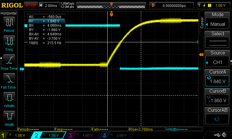
The answer is an inverting Schmitt trigger, an integrated circuit that shifts from 1 to 0 at some higher threshold, and from 0 to 1 at a lower threshold. It’s an inverting trigger, which means that it’s output is always the opposite of the input, as seen in the image above. The yellow line is from the RC circuit which is the input to the trigger. For the trigger, I’m using a 74HC14, an integrated circuit (i.e., a chip) which switches from high to low when the input voltage hits about 1.8v (when the input voltage to the chip is 3.3v).
Note that as the yellow line gently climbs, when it hits 1.8 volts, BAM, the Schmitt trigger output shown by the blue line drops from HIGH to LOW. The datasheet reports that the drop happens in about 7-19ns; My oscilloscope sees the transition in 14.8ns: good job, datasheet. By comparison, the CPU on the Teensy is running at 600mHz, which means about one cycle takes 1/600th of a million-th of a second, which is approximately 2 nanoseconds. While it only takes one cycle to read the digital pin (in the very best case, usually it’s more), the Arduino is doing other stuff and can’t check the pin every cycle, so it won’t read the pin more than every 50-100 ns. The Schmitt trigger switches in about 15ns, 8x slower than the CPU. There’s very little chance chance that the Teensy will be confused during the trigger’s transition.
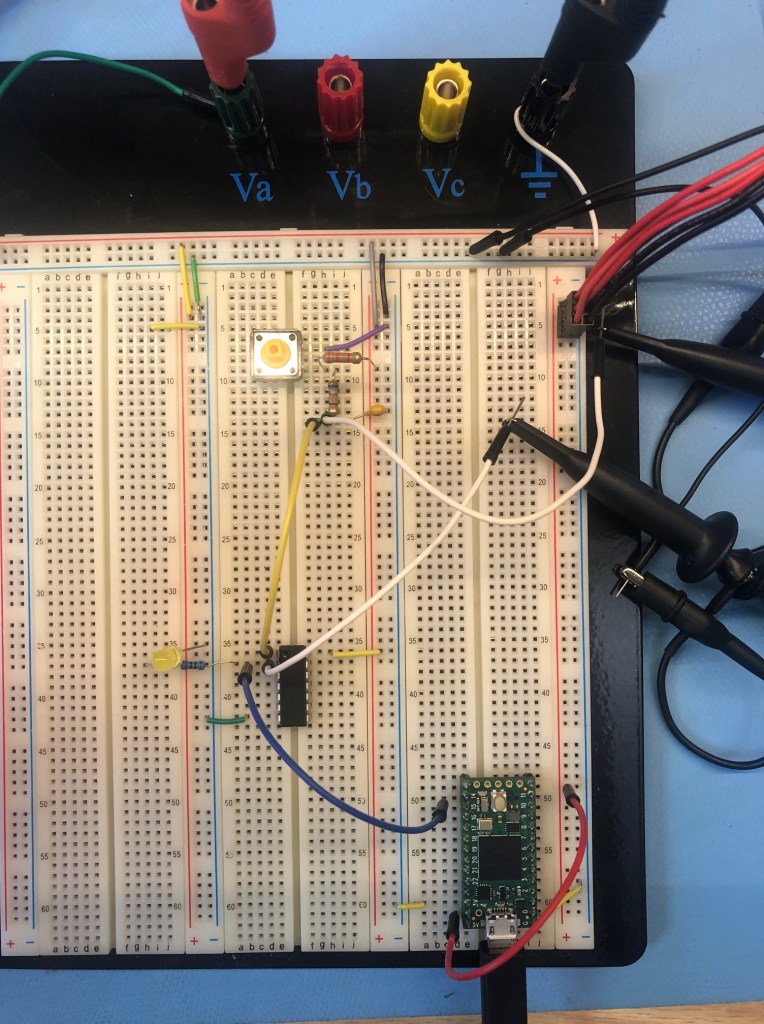
Here’s what it looks like wired.
The code that runs the counter is below. I’ve banged on this button something fierce, and it counts once and only once every time I hit it. There’s no software debouncing at all, the hardware is doing all the work.
I like it! It’s pretty unnecessary: I’ve found that a simple delay works for nearly all my applications, and in exceptional cases like rotary encoders, state machines work a treat. However, I’m really happy to have had a reason to look more deeply into this topic and to have another tool in my kit if a switch acts up.
/*
   testing button press counts
   wylbur, 25 Dec 2019
*/

const int CHIP_PIN = 15;
int chip_count = 0;
int last_chip_count = -1;

void setup() {
  //start serial connection
  Serial.begin(57600);
  pinMode(CHIP_PIN, INPUT_PULLDOWN);
  attachInterrupt(digitalPinToInterrupt(CHIP_PIN), isrChip, RISING);
  Serial.println("init complete.");
}


void loop() {
  if (chip_count != last_chip_count) {
     Serial.print(millis());
     Serial.print(F(": chip="));
     Serial.println(chip_count);
     last_chip_count = chip_count;
  }
}


void isrChip() {
  chip_count++;
}

// done.