
This video is an example of my questions on this thread at the Adafruit forum.
Archives for the month of: August, 2013
The power and ground wires are getting set up in the blinky coat.
 Here the conductive thread is sewn through the coat, looping a pad from each NeoPixel to the appropriate power or ground wire. As noted in an earlier post, the power and ground wires have little cuts in the insulation so the conductive thread can make the contact. Here’s an overview of how things are as of yesterday:
More to come!
As in last year’s model, the LEDs draw 60mA (at 5V) per pixel. I’m now planning 76 pixels, so that’s about 4.5A — if they were all on bright white at the same time, which is rare. Nonetheless, that’s a lot of power.
I’ll bring the power from the battery to the pixels in buses, that is, relatively thicker wires (22AWG) that can handle the current. The positive (red) and ground (black) have little cuts in the insulation through which the conductive thread wraps each pixel to each bus. Here’s an image of the buses:
 After I marked them, I used a wire stripper to make a little break at each mark. Then I separated the sections of insulation just a tiny bit, lining them up, so the pixels can be wired into them.
The buses connect to the battery through voltage regulators that bring the power from whatever it is at the battery (7.2V in the batteries I’ll use in the coats, but 8.4V in the battery I’m using for testing) to stable 5V that the LEDs need. The FLORA can take whatever voltage we give it. The wiring from the battery looks like this.
 Starting on the far right, the molex plug connects to a battery. The negative (black) wire goes to the wire snap on the top; the wire snap connects all the wires in the snap: the battery ground, the ground wires for the input for the 3 regulators, and the ground for the JST that powers the FLORA. The red wire for the molex connects to the positive for the 3 regulators, and the positive for the FLORA.
The regulators each handle about 1.5A, so we use three of them. We’ll bring the positive from each regulator to a subset of the LEDs. The ground is common for all of them. The 4-pin JST on the bottom left will connect to wires that carry the current to the buses on the back of the coat.
Here’s an overview:
Last year’s evapotrons got rid of a lot of grey water, on the order of 175 gallons. Good, but I think the design suffered from the Arduino (from my code, anyway). The machine crashed a lot and got into weird loops, so the control devices I built ended up leaving the pump not running for chunks of time.
New attempt: we’ll just let the pumps run all the time. They’re not loud, and they don’t draw all that much power (about 25w each). No Arduino.
Also we realized that without the Arduino, the evaporation towers can sit in a single kiddie pool (we don’t need the two-stage mechanism we had last year). That means each tower can be made of deer wire and rebar. Here’s the structure:
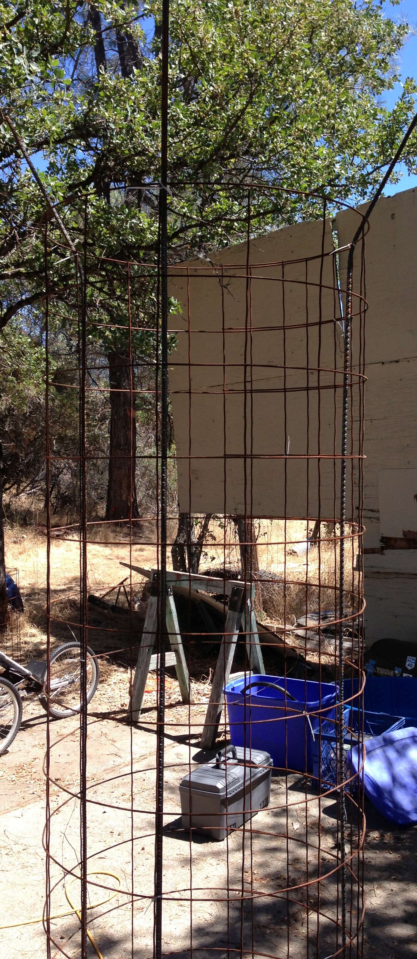
In the image, you can see the deer wire formed in a 7′ tall, 36″ diameter cylinder. At three equilateral points, a piece of 8′ rebar will be fixed to the deer wire to give it more vertical rigidity. The cylinder will be wrapped in burlap.

The rebar comes out of the cylinder at the top. From each rebar top, we’ll fix a line of webbing down to the truck, kind of like the diagram below.

Last year we used a strap of webbing wrapped around the truck to anchor the evapotron to the truck. This year, we’ll have 3 straps around the truck. Each evapotron will attach to the straps by 3 guy-ropes: one toward the center, and two to the front or rear corners. The guy ropes are 1000-lbs test ratcheted tie-downs, so I think they’ll hold fine. The guy-ropes also provide a way to level the top of the evapotron, which turns out to be Very Important.
We’ve also improved the water distribution mechanism on top of the saucer. Note the PVC is all fitted and glued.
 Underneath the saucer, the PVC attaches to a simple hose that drops to the pump sitting in the kiddie pool. No Arduino, though I may yet add an Arduino to drive some blinkies to show off the evapotrons. More to come.
I had kind of given up on last year’s attempt to make a coat covered in swirly bright LEDs. We made the coats, but they were way, way, way too heavy to be usable. The coats themselves were pleather & (fake) fur, so they were hot. Then 200 pixels, a 6-lbs battery, and very fragile wiring made them unusable.
Try again! Adafruit’s NeoPixels are sewable and designed for wearable applications. I got to thinking: hmm, what if only 60 pixels? What if the pixels were all together (making layout simpler)? What if we just run super-simple patterns? Ok, back at it. 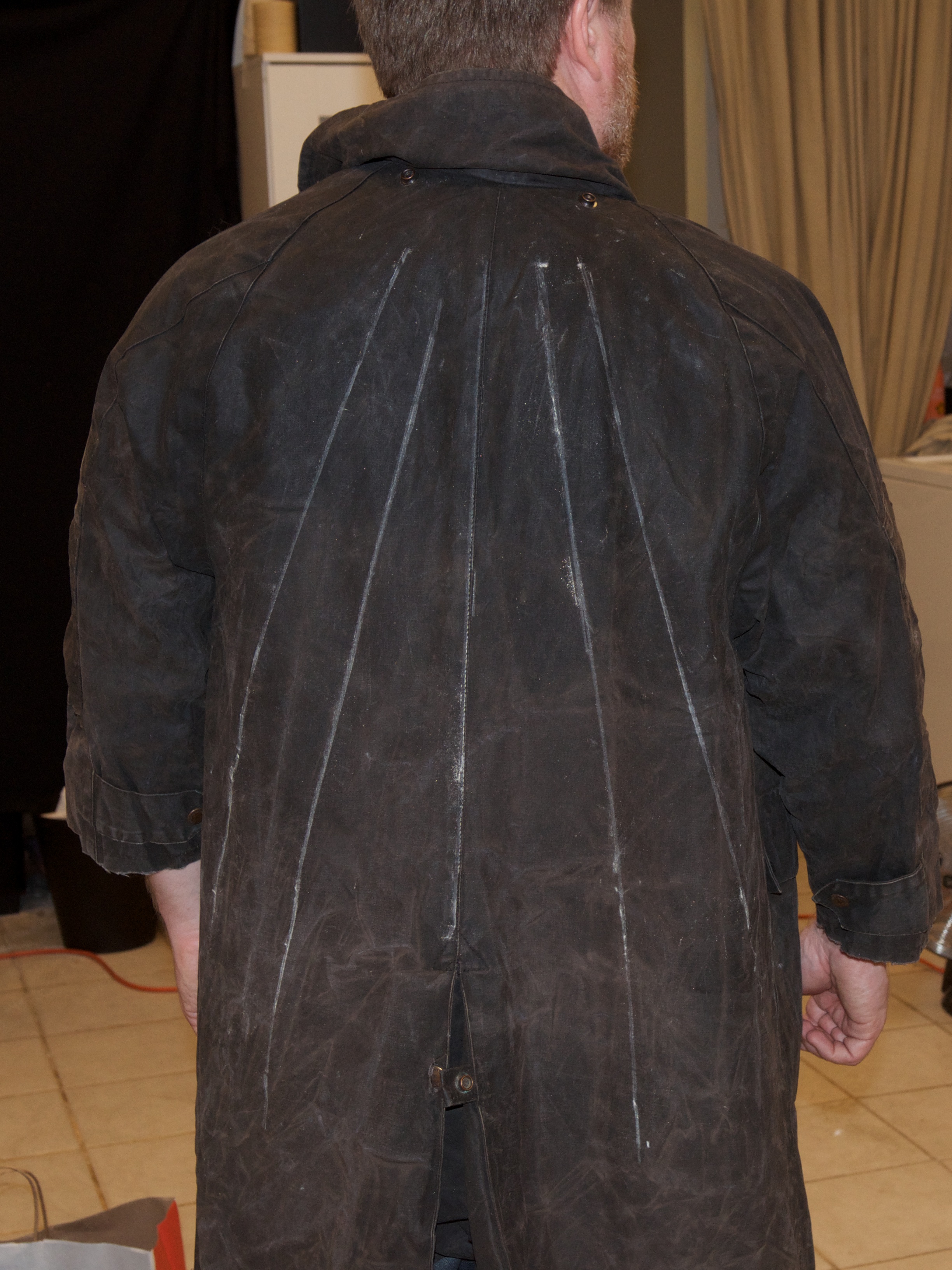
I found an Australian cattle-driver’s coat at a school rummage sale in Vermont, and my friend the experimental seamstress laid out a nice pattern (see photo and diagram).

More images as we finalize the power and ground bus and the wiring.
