Archives for the month of: August, 2012

It seems like it’s actually working in this 45Ks (nearly 13 hours) run:

This is Box B, so it’s nice to see that it’s doing ok. The point here is that the batteries are handing off to each other smoothly. Note that if the bus battery runs out of power, it does a bunch of very short pumping cycles (see from 20-23Ks). This isn’t very effective, I don’t think, but it’s still probably the preferred behavior.

One slightly worrisome note: I’m clearly not sensing the charging cycle correctly. Note that the charging graph climbs, holds the peak, then drops to a plateau for a while (3600 seconds, actually) before handing off to the other battery. The handoff is being triggered by logic that notes a long plateau in the charging voltage. Somehow the logic that spots the peak and descent between phases 2 and 3 isn’t working. So time is being wasted while the plateau-sensing code waits to make sure this is a real shift to charging phase 3.

Maybe I should sense the slope of the charging cycle? Or just shorten the time the plateau is being watched? Dunno, but either way, the charging cycle can be shortened by at least 1800 secs, maybe even 3000s.

That’s it, testing time is exhausted. Time to go to the playa.

Most things are working properly:

The battery switching looks good. However, the pump hung at time==14617. At that point, for its own reasons and without input, the flow sensor decided that the flow rate is infinite. There’s a bug in it’s calculations, but whatever, at this point I have to ignore the flowrate calculation in the code from Adafruit, and monitor the flow sensor’s pulse count directly.

I did a six hour test run of the evapotron control circuit today, with mostly positive results.

This graph shows the bus voltage, the depth in the reservoir, the current drawn by the pump (in mA), and the voltage in the circuit being charged. It all makes sense, but it might benefit from a walk-through.

The bus voltage declines over time, of course, because this is the battery being drawn on to run the system. Periodically it drops about 0.8v — which is when the pump switches on. The depth stays roughly constant at about 25cm of water in the reservoir, which I’m measuring by using a load sensor. The pump can push water up faster than it returns, so occasionally the pump doesn’t finish it’s cycle before it runs out of water; those are the interrupted cycles. The current in the third panel is the inverse of the bus voltage and depth curves: it’s high when the pump’s running, and otherwise just noise and leakage (this is a little troubling but may just be sensor noise).

Then the charging circuit reminds us how three-stage lead-acid battery charging works. I’m watching it for when it drops back to 13.75v, which is when it hits stage 3. At that point, the battery on the bus could hand off to the newly charged battery, and charge itself.

This cycle doesn’t work the pump hard enough. I’m off until Monday, but I’ve got a couple of days to tune the work-charging cycle to find the max time the pump can run matched to the battery charge time.

Oh, and the second evapotron? Not done, but it’s close. The data logging shield for the Arduino doesn’t work (we’re debugging on the Adafruit forums); the sensor cables aren’t made, and the whole thing isn’t tested. I wish I were substantially farther along, but it’s all going to have to be enough.

(I have a long blog rant coming about how hard it is to measure liquid depth — the eTape failed; the Ping))) failed; and various attempts to test resistance of the water all failed)

if banshees were into hobbyist electronics, anyway.

Hard to see in the blurry photo, but this is the third coat, running. The three Otter-boxes housing the Arduinos are on the mat (only one is working, the other two have their signal and power cables flopped out).

It’s been a long road, and I still don’t have software or a control system. Each control box has a 4-bit dip switch to choose alternative programs, and a potentiometer knob for varying the refresh/flash speed. However, I’ve written software for neither.

I dumped a strand and Arduino on my friend Slobberchops, he’s an Alpha Geek. I’m hoping he gets interested enough to write me some cool patterns in the 10 days before I leave for the playa. Holy cats, only ten days; I’m not panicking, breathing, calm.

One of the three LED blinky coats is now working.

But there’s no real software on the Arduino yet, just DBU’s demo. And the various controls I plan aren’t in place. Still, it’s been a bear to get this far. The LED strands are physically robust, but electrically very very fragile. I’ve now fried four of them. However, I think I’ve got the handling figured out. Most of the errors were just plain boneheaded, and these things are not forgiving.


My project partner P has done a brilliant job with the evapotron’s physical part. It starts with a platform:

The kiddie pool and the mesh tower sit on the platform, and the reservoir and pump are underneath.

In this shot, you can see the green filter bucket in the lower right (on top of the white bucket); the tower on the platform in the center; and the green reservoir bucket underneath the platform. The idea is that the water is pumped from the reservoir up a pipe running through the center of the tower and over the saucer on top. The water trickles down the tower, wetting the burlap. Here’s a shot of the drive pipe, the pump attaches at the bottom.

The tower is made of a heavy interior mesh (approx 16ga wire in 6″ squares — it’s fencing). Then the burlap is wrapped around, then a thin screening mesh is on top of the burlap. The whole thing is held together with zip-ties.

We found that it was important to draw channels on the saucer (in silicone) to get the water flowing evenly across the saucer. Otherwise (and perhaps even so), we’ll be shimming under the platform endlessly, trying to get it level.

(There is another option — to use a rotating sprinkler head inside the tower — which avoids the need to level. However, this leaves the saucer dry, and I suspect that the saucer is a big contribution to the evaporation. This may be testable.)

P packed it and hauled it to our campmates’ staging area near Reno. Now if only I can finish the control units, we’ll have data and control of the charging. Time is short.

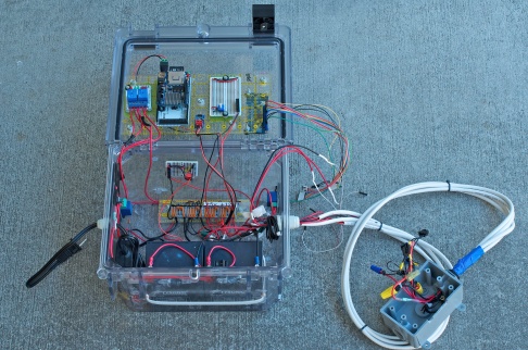
The grounds from the batteries go to all three GND wire snaps. From there, grounds also go to the two perf boards. The Arduino will also connect via ground leads to the ground rails on each perf board.

There are three DC positive systems: +12v, +5v, and charging, and each has a wire snap joining its components.

+12v power from the batteries first goes through a DPDT switch (so I can cut off the batteries physically) to the common pole in two relays (each battery to one relay). The relay’s normally closed (NC) pole connects to the +12v bus, and the NO pole connects to the charging circuit.

The +12v bus supplies the Arduino, a voltage sensor, a line to the pump (see below), and a voltage regulator.
Image
The voltage regulator supplies the +5v bus. This bus supplies power to the two perf boards, each of which has 8 F headers (for the sensors in the control box, and for the LCD). The +5v also connects to the +5v line for the junction box (for the sensors in the reservoir).

The +12v line for the pump goes through a current sensor and then to a relay which controls when the pump is on or off.

The charging circuit connects the leads from the batteries’ relays to the charger. There’s also a voltage sensor.

The logic: the Arduino can choose whether the batteries are connected to the +12v bus or to the charger. Of course, one battery has to be on the +12v bus all the time, or the Arduino will lose power. If it does, both batteries will revert to the bus anyway (the bus is on the NC pole of the relays), but the Arduino will reboot.

When one battery is connected to the charger, a voltage sensor will tell the Arduino how the charging cycle is going.

The +12v bus is monitored by a second voltage sensor, so the Arduino knows the level of the power in the system.

The Arduino can use the fourth relay to turn the pump on and off; whatever the pump draws is monitored by a current sensor.

Whew! And that’s before any of the logic wiring goes into place. Getting close, though.