So I’ve wanted to do a project that accomplished several goals. First, I need more blinky stuff in my lab. What good is a lab if there aren’t bunsen burners bubbling, inscrutable machines whirring, and, best of all, little lights blinking?
Second, I wanted to learn how to use basic integrated circuits, and one of the most useful and classic is the 74HC595. This chip is a shift register which means that it takes a serial input and writes it to 8 parallel outputs. You can chain several of these together, and so still using only 3 wires from a microcontroller (like an Arduino, which is what I’m using here), drive 24 signals. Here’s what it looks like on an oscilloscope:

These are the signals from the Arduino to the 74HC595. Let’s read the oscilloscope from the bottom up. The purple line is the latch. When this signal is pulled LOW, the 74HC595 listens for data. The blue line in the middle is the clock: when it rises from LOW to HIGH, the 74HC595 checks the input signal. So when the blue line rises on the left, the 74HC595 checks the signal measured by the yellow line (called serial), and sees that it’s HIGH. That’s a 1. The blue line cycles down, then back up, and the 74HC595 reads again: another 1. And so forth, in my case, for 24 bits.
When the latch is set, the bits are pushed into the chip. Each 74HC595 only remembers 8 bits, so if there are more, it pushes the rest out on pin 9, called $Q_H’$, which is read by the next chip (if there is one). I chained 3 chips together, thus 24 bits in each latch-unlatch cycle. This all happens in about 450 microseconds, which is pretty fast for people, but pretty slow for electronics (this means we could only do about 2000 of these cycles per second). This chip was invented in the early 1980s, though there were very similar versions long before this time. I think it’s amazing to use something from that era for a useful purpose now.
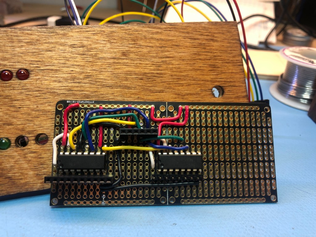
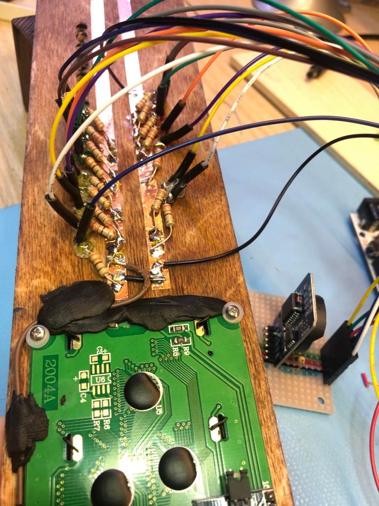
To build this, I need a way to take the 3 signals from the Arduino to the 3 chips. After a lot of prototyping, I wired the chips together with a header for the Arduino (in the middle of the wires) and with headers for the LEDs (below the chips) together on this great strip board. This photo is when two of the chips are soldered, waiting for the third.
Of course I need a clock. I used a cheap DS3232RT with this library. We’re going to need to introspect a little bit, so I added a somewhat clunky but entirely functional 20×4 LCD screen that speaks I2c. And I added a giant, blinking arcade button.
I spent a long time figuring out the layout. I should have done this with some kind of modeling software (which I really need to learn so I can do CNC milling and 3d printing), but I just Old Skool drafted it.
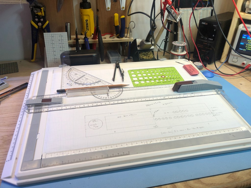
I put the enclosure together in a bit of 1/4" hobby plywood from the hardware store, stained to look like it isn’t totally crappy. One of the pieces that took me longest to figure out is how to cut a hole out of the middle of the board, and make it square and parallel. This wasn’t easy because I’m a seriously crappy craftsman.

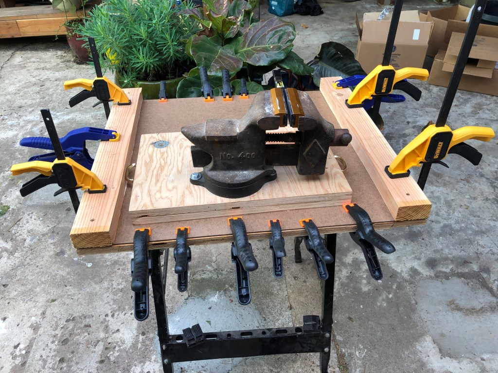
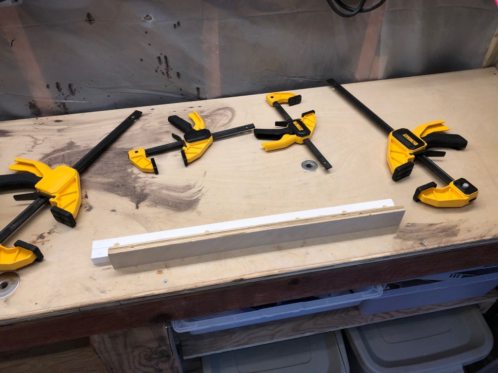
The basic idea is to drill 3/8" holes in the corners, then use a jigsaw to cut between the holes. I built three different jigs to try to get cuts straight and square. Nope, then nope, then nopest. Finally I saw a YouTube video (which I’ve now lost) that said, like everybody just knows this, to put the panel on a vise, then file the sides flat and square.

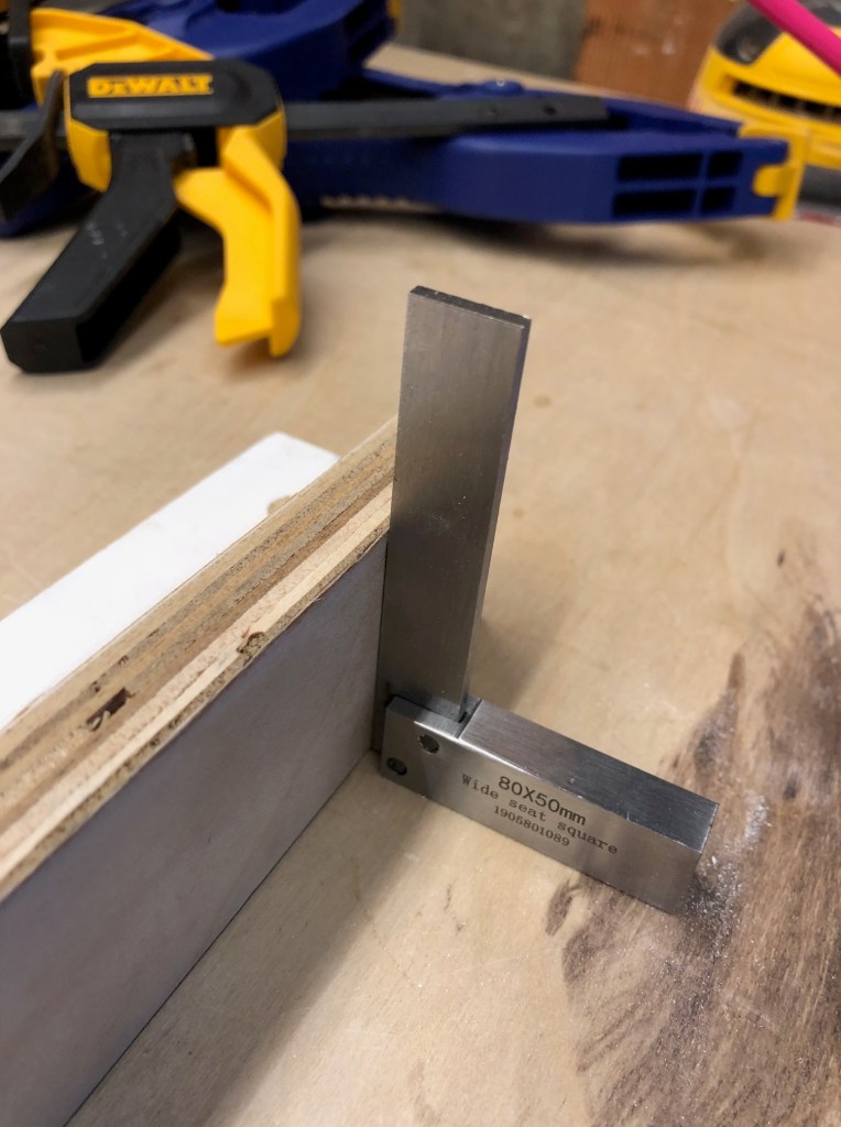
The key I discovered is to cut rough using the technique above, but then put aluminum L stock on the vise jaws, and align the panel with the L stock up just barely under the mark for the edge of the hole. Then file the wood flat to the L stock, and the filed line with follow the line of the L stock. If I’ve set up the L stock up correctly, we’ll get a good square. It worked! The hole is square and parallel to the board used for the front panel. And now I have a set of Very Serious Nicholson files (I love good tools so much). The LCD dropped nicely into the hole, and I secured it there with some sugru and a few tiny screws. The LCD shows the decimal and binary values for each of the four variables shown by the LEDs as a kind of cheat sheet.

I mounted the LEDs into the front panel with hot glue. Note to self: big LEDs fit perfectly in a hole 13/64", while the little LEDs slot into a 1/8" hole.
I put a 330Ω resistor on each LED’s cathode and then soldered it to strips of copper tape I affixed to the back of the front panel as a ground bus. I put pre-crimped leads from Pololu on the anodes. I organized the wires in connector housings that I could attach to the PCBs. I made 3 bundles of 8 wires (one for each 74HC595) plus a ground wire.
There are 2 boards: one for a I2c bus for the clock and the LCD, and a pullup resistor for the button; and one for the 74HC595s.
The front panel is connected to the back by 1/4" bolts through little blocks I cut out of 2x4s. A bolt through the back panel, the block, and the front panel with an acorn nut holds it all together. Perhaps I’ll cut acrylic sheet for the currently-open sides.
It works! I’ll post the code below until such time as I get a minor GitHub repo set up. I’m grateful to Slobberchops for his help: I’ve never sliced bytes and twiddled bits before (I live a little higher in the stack), and I’m delighted to have done it with his help. I hope to make this compile with arduino Makefile. That’s the next rev, and I’ll update this post with a GitHub link when I get this a little cleaner.
/*    Author: wylbur  https://wylbursinnergeek.net
 *
 *    Date: 2020-04-23
 *    License: GPL v2+
 *
 *    building on the shoulders of others. Thanks.
 *
*/

#include <Wire.h>
#include <LiquidCrystal_PCF8574.h>  // https://github.com/mathertel/LiquidCrystal_PCF8574
#include <DS3232RTC.h>              // https://github.com/JChristensen/DS3232RTC
#include <FastLED.h>

#define DEBUG 1
#ifdef DEBUG
  #define DEBUG_PRINT(x) Serial.print(x)
  #define DEBUG_PRINTLN(x) Serial.println(x)
#else
  #define DEBUG_PRINT(x)
  #define DEBUG_PRINTLN(x)
#endif


const int ledPin = 3;
const int buttonPin = 2;
const int dataPin = 7;
const int latchPin = 5;
const int clockPin = 6;

LiquidCrystal_PCF8574 lcd(0x27); // set the LCD address to 0x27 for a 16 chars and 2 line display

// https://stackoverflow.com/questions/111928/is-there-a-printf-converter-to-print-in-binary-format
// part 1
const char *bit_rep[16] = {
    [ 0] = "0000", [ 1] = "0001", [ 2] = "0010", [ 3] = "0011",
    [ 4] = "0100", [ 5] = "0101", [ 6] = "0110", [ 7] = "0111",
    [ 8] = "1000", [ 9] = "1001", [10] = "1010", [11] = "1011",
    [12] = "1100", [13] = "1101", [14] = "1110", [15] = "1111",
};


boolean fadeDirection = 1;
byte fadeValue = 0;

volatile boolean displayMode = 0;
boolean lastDisplay = 0;
volatile unsigned long last_button = 0;
int last_second = -1;
unsigned long last_us = -1;

char line1[21] = "";
char line2[21] = "";
char line3[21] = "";
char line4[21] = "";
byte r1 = 0;
byte r2 = 0;
byte r3 = 0;
byte days;
byte hours;
byte mins;
byte secs;
byte dd;  // 5 bits
byte hh;  // 5 bits
byte mm;  // 6 bits
byte ss;  // 6 bits


void setup() {
  Serial.begin(9600);
  delay(250);
  Wire.begin();

  attachInterrupt(digitalPinToInterrupt(buttonPin), modeSwitch, FALLING);

  pinMode(latchPin, OUTPUT);
  pinMode(clockPin, OUTPUT);
  pinMode(dataPin, OUTPUT);

  DEBUG_PRINT("LCD...");
  printf_init(lcd);
  Wire.beginTransmission(0x27);
  int error = Wire.endTransmission();
  if (error == 0) {
    DEBUG_PRINTLN(": LCD found.");
    lcd.begin(20, 4); // initialize the lcd
    lcd.setBacklight(255);
    lcd.home();
    lcd.clear();
    lcd.setCursor(0, 0);
    lcd.print("Hello binclock");
    // lcd.setCursor(0, 1);l
    // lcd.printf("hello world %d\n", 42);
    delay(2000);
  } else {
    DEBUG_PRINTLN("LCD not found.");
  }
  setSyncProvider(RTC.get);   // the function to get the time from the RTC

  #ifdef DEBUG
  if(timeStatus() != timeSet)
    Serial.println("Unable to sync with the RTC");
  else
    Serial.println("RTC has set the system time");
  #endif

  lcd.clear(); lcd.noDisplay(); lcd.setBacklight(0);
}


#ifdef DEBUG
unsigned long loopctr = 0;
#endif

void loop() {
    EVERY_N_MILLISECONDS(25) {
      if (displayMode == 0) {
          if (fadeDirection == 1) {
            fadeValue += 3;
          } else {
            fadeValue -= 2;
          }
          if (fadeValue >= 150) {
            fadeDirection = 0;
          } else if (fadeValue <= 0) {
            fadeDirection = 1;
          }
      } else {
          fadeValue = 0;
      }
      analogWrite(ledPin, fadeValue);
    }

    #ifdef DEBUG_A
    Serial.print(fadeValue); Serial.print("  ");
    Serial.print(fadeDirection); Serial.print("  ");
    Serial.print(displayMode); Serial.print("  ");
    Serial.print(millis()); Serial.print("  "); Serial.println(last_button);
    #endif

    EVERY_N_MILLISECONDS(50) {
      byte secs = second();
      if (secs != last_second | displayMode != lastDisplay) {
        time2bytes();
        bytes2serial();
        update_lcd();
        last_second = secs;
      }
    }

    #ifdef DEBUG
    EVERY_N_MILLISECONDS(1000) {
      Serial.print(fadeDirection); Serial.print("  ");
      unsigned long us_elapsed = micros() - last_us;
      Serial.print("us_elapsed="); Serial.print(us_elapsed);
      Serial.print("; loops in elapsed="); Serial.print(loopctr);
      float loops_per_ms = loopctr/(us_elapsed/1000);
      Serial.print("; loops_per_ms="); Serial.println(loops_per_ms);
      last_us = micros();
      loopctr = 0;
    }
    loopctr++;
    #endif

}


void bytes2serial() {
  // push r1,r2,r3 to serial.
  digitalWrite(latchPin, LOW);
  shiftOut(dataPin, clockPin, LSBFIRST, r3);
  shiftOut(dataPin, clockPin, LSBFIRST, r2);
  shiftOut(dataPin, clockPin, LSBFIRST, r1);
  digitalWrite(latchPin, HIGH);
}


void modeSwitch() {
  // it's a very noisy button
  if (millis() > last_button + 300) {
    displayMode = !displayMode;
    last_button = millis();
  }
}


void time2bytes() {
   days = day();
   hours = hour();
   mins = minute();
   secs = second();
   dd = days & 0x1F;  // 5 bits
   hh = hours & 0x1F;  // 5 bits
   mm = mins & 0x3F;  // 6 bits
   ss = secs & 0x3F;  // 6 bits

   r1 = (dd << 1) & 0xFF; // r1 has the rightmost 7 bits of dd (first two are 00)
   r1 |= (hh >> 4);       // hh is only 5 bits, so right shft 4 puts hh's first bit at end of r1
   r1 |= 0x80;           // to set only first bit
   /*
   r1 |= 0xC0;  // to set both first bits on
   r1 |= 0x40;  // to set only second bit
   */

   r2 = (hh << 4) & 0xFF; // hh is 5 bits, so left shift 4 leaves bits4-7 at left of r2
   r2 |= (mm >> 2);       // getting the left 4 bits of mm (first two are 00)
   r3 = (mm << 6) & 0xFF; // rightmost 2 bits of mm
   r3 |= ss;              // ss is 6 bits wide and all go here
}

void update_lcd() {
   if (displayMode == 1) {
      sprintf(line1, "  dd: %02d  %s%s", days, bit_rep[dd >> 4], bit_rep[dd & 0x0F]);
      sprintf(line2, "  hh: %02d  %s%s", hours, bit_rep[hh >> 4], bit_rep[hh & 0x0F]);
      sprintf(line3, "  mm: %02d  %s%s", mins, bit_rep[mm >> 4], bit_rep[mm & 0x0F]);
      sprintf(line4, "  ss: %02d  %s%s", secs, bit_rep[ss >> 4], bit_rep[ss & 0x0F]);

      if (lastDisplay != 1) {
         lcd.clear(); lcd.display();  lcd.setBacklight(255);
         lastDisplay = displayMode;
      }
      lcd.setCursor(0, 0);   lcd.print(line1);
      lcd.setCursor(0, 1);   lcd.print(line2);
      lcd.setCursor(0, 2);   lcd.print(line3);
      lcd.setCursor(0, 3);   lcd.print(line4);

    } else {
       if (lastDisplay != 0) {
           lcd.noDisplay(); lcd.setBacklight(0);
          lastDisplay = displayMode;
       }
    }
}


// done.