Archives for the month of: August, 2016

The animatronic tail I’m making for ❤ has a pretty simple UI: there’s one button. If you push the button, the tail wags. But if you double-click the button, the tail goes nuts.

Alas, buttons are noisy. As the button is pushed or released, there are many tiny little voltage surges as microscopic ridges and grooves in the switch touch and release as the connection is definitively made or broken. The Arduino sees these little surges and drops and thinks that the button is being pushed and released a few times in 10-20 milliseconds. This is called bouncing, and it is a Bad Thing.

There are tons of approaches for debouncing buttons in software. These all basically come down to ignoring the button for a while after detecting a change. That means that any additional real button presses also get ignored. It’s pretty hard to get the software tuned to ignore bouncing but detect double-clicking. People claim to have done it, but it didn’t work for me.

Debouncing in hardware is a little more involved: it involves building a small circuit with a resistor, a capacitor, and an op-amp integrated circuit. The circuit is called a Schmitt trigger, and the point is to sharpen a noisy set of voltage shifts into a nice square wave: either the button is pushed or it is not pushed, there is no bouncy jiggling.

There are several ways to build a Schmitt trigger, and my hack is shown in the photo. I used a 10KΩ resisistor, a 10㎌ capacitor, and a LMP358 op-amp chip.

IMG_2385

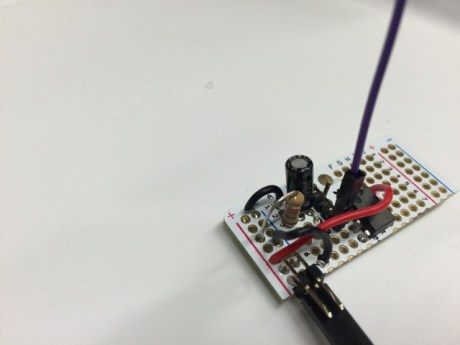
I got the design from Jeremy Blum’s excellent tutorial on this topic. I’ve tested it, and it works incredibly well. Very smooth, no extraneous clicks, and the software no longer has to ignore the button in delay patterns. Yay!


Once upon a time, someone said about Unix regular expressions that if you think can can use them to solve a problem, now you have two problems. What he meant is that regexes are at the same time so powerful and so complicated that they’re hard to debug and hard to be sure that you know what they’re really doing. I feel that way about dremels.

IMG_2379

I use the dremel to cut stuff, like plastic boxes, and in this case, a seriously overspec’d steel motor mount I’m using to fix a stepper motor in a little box to create an animatronic tail for my ❤.

But whenever I get the dremel going, I feel like it’s within an instant of flying to pieces, maiming me, and more importantly, like it might damage whatever I’m cutting. A safety course might be helpful, someday.

I’ve been pretty curious how much energy the mirror uses. However, it’s taken me a long time to figure out how to measure it. For unrelated reasons, I’ve got an arduino that I figured I can use for the voltage measurement.

IMG_2382

The power to the Arduino comes straight from the batteries, so I put a little voltage sensor across the battery feed’s positive + negative. It sends an analog signal to the arduino, and the arduino parses the analog input and sends sends logging info to the Raspberry Pi via a serial connection (note that the Arduino is set to 3.3v! otherwise the serial connection could damage the Pi).

There’s a daemon running on the Pi that parses the Arduino’s serial feed and writes tiny data files to a tmpfs dir. Each time the data reading daemon runs, it writes a file to the tmpfs with one line of data (actually, it writes a temp file then renames it; renaming is atomic, and so avoids a race condition between the serial parser and the data readers). Another daemon reads the data line and logs it. The two-part process means that one daemon can parse the serial data while several others consume it.

In this case, we want the log of the voltages. I set up the test with a single fully-charged battery (a 12v/100Ah deep cycle). Here’s what I found:

blinkybox-volts-by-hours

The mirror ran for over day! That means that having two batteries that are charged by solar during the daytime is much more capacity than we need to run it for 10 hours at night. Good.


One of my favorite project batteries is this 7.4v/4.4Ah Li-ion from BatterySpace. It’s basically four 3.7v batteries (approximately AA sized) packed in heavy shrink wrap.

IMG_2380

The original is the white and green on the left. I needed it to fit the form on the right so it will sit nicely in the project box for the animatronic tail. So I cut it open, and found a little more complexity than I expected.

The batteries are in two packs of 2 each, wired in parallel; the packs are then wired in series. They connect to a little PCB that adds charging and short protection.

The trick is that the batteries have foil tape for the contacts, and I couldn’t figure out how to solder to the foil. I made 3 copper plates with solder blobs for contacts. All 4 batteries connect on one end (two negative and two positive) with a square copper plate. The solder blobs on the plate press into the battery contacts, and I taped it tightly. I soldered a wire to the plate which connects to the common pad on the PCB.

On the positive and negative ends, I did something similar with two rectangular copper plates, one taped across the two positives, the other across the two negatives. Lots of tape prevents shorts, and now I have a battery that fits nicely in the box.