
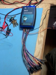
I got a ADALM2000 from digikey. It arrived quickly and without incident.
This device connects to a computer via USB and enables a lot of different measurements and kinds of signals. It doesn’t have a screen or controls, everything happens through the software on the laptop. I’ve been shopping for an arbitrary waveform generator, and this little box offers a pretty solid set of features for waveforms. In addition, it has a ton of other features, some of which I didn’t know about. It’s just arrived, so let’s take it for a spin.
First, I’m using this on MacOS 10.15.3, and the documentation says to install device drivers so the M2K is recognized by the operating system. The software they suggested gave errors when I tried to install it, but it turned out to be unnecessary anyway. I installed the control software, Scopy. And as all the best YouTubers say, let’s get started.
The device was incredibly easy to install and attach, so I’m going to skip that part. We forget about the stuff that Just Works. It’s a little annoying to have to figure out which of the many F dupont leads is the one I’m supposed to use for each feature, but I suspect I’ll just leave more useful leads in the appropriate connections.

The oscilloscope is the first tool. I attached it to my oscilloscope’s signal generator which emits a constant 1kHz square wave. And it looks exactly right. I didn’t play with the triggers, but the timebase and the volts/division were easy to set. Even easier was the autoset feature – it made a pretty good decision. I can imagine all the rest of the oscope stuff working pretty easily.
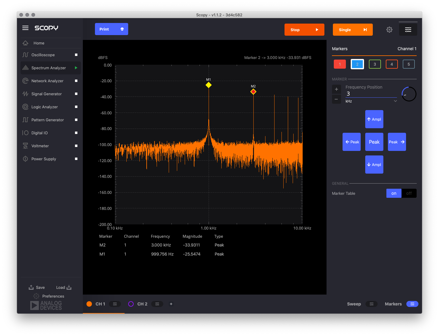
The network analyzer is another tool I’ve never used before. As far as I can make out, it’s basically a tool to test electronic filters. It generates a "stimulus" which it puts into the circuit. We measure the circuit at it’s input (going into the resistor) and its output (at the junction between the resistor and a capacitor). The resulting curve on the response channel shows how different frequencies are permitted or attenuated by the filter. The filter I put together (with a 1K resistor and a 2.2nF cap) starts attenuating at 1kHz and is strongest at 10MHz. Interesting.
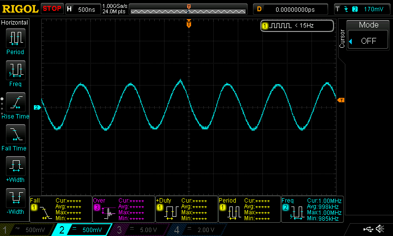
I bought this thing for the waveform generation. I attached the W1 lead to my oscope’s lead, and GND to GND. I set it to a sine wave at 1kHz at 1v peak-to-peak, and it’s dead on. It’s also dead-on at 1MHz (shown), but it tops out at 30MHz, and at that speed, the signal is a tiny bit wobbly. To be fair, these are unshielded leads, and I think this speed is pushing my oscope’s ability to capture the signal reasonably, so I’m impressed.
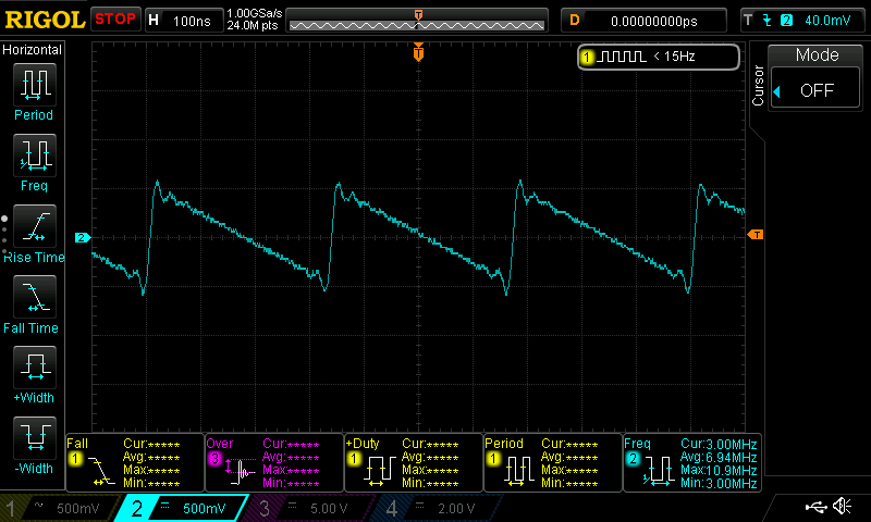
The square wave is a little less stable. At 10MHz it’s a wobbly mess. However, by 1MHz, it looks square and stable. Similarly the triangle was wobbly at 10MHz but looks great below around 4MHz. In the image below, the sawtooth at 3MHz is a little wobbly.
There are the usual waveforms (sine, square, triangle, sawtooth) and options to input user-generated waves or output from math functions. This is exactly what I wanted. Just this is enough to make me pretty happy with this device.
The logic analyzer might for me be this device’s killer app. This is for figuring out whatever is going on in digital signals. I want to know.
I’ve been playing with some APA102 LEDs (Adafruit calls these DotStars) and a Teensy4. I write into the LEDs using the FastLED library. The protocol that the software on the Teensy uses to shove bytes down the wire is called SPI.
The wires that go to the LED strand go through a chip called a 74HCT245. This chip shifts the voltage from a barely readable-400mV to a stable 0/5v LOW/HIGH pattern. I’ve been curious if anything else happens in this chip, like say, a bunch of noise.
The logic analyzer lets me read the signals as they go through the line. Even more cool, it freakin’ decodes the signals so I can see what’s going on. In th eimage below, channels DIO1 and DIO3 measure the clock signal. Whenever the clock rises, the LED chips read the signal (HIGH or LOW) on the data line (which is measured on DIO0 and DIO2). Signals DIO0 and DIO1 are measured coming out of the Teensy, while DIO2 and DIO3 are measured coming out of the 74HCT245. This enables me to compare the two to see if they differ.

All this is happening one million times per second. Wow. This is a great tool.
The pattern generator creates digital patterns like the ones that the logic analyzer reads. In some sense, a signal generator is to an oscilloscope as a pattern generator is to a logic analyzer.
The digital IO is pretty easy to figure out: you can put a 5v signal on a channel, or measure one. Since there are 16 channels, that makes this a pretty convenient breadboard helper.
The voltmeter is interesting. First off, it’s helpful to have two channels. But be clear: this is a "voltmeter" in a sense similar to Adafruit’s fantastic ina260 measurement board. It’s delicate, will fry from reverse voltage, and has a very limited range. And it’s not all that accurate.
I connected the Adafruit LM4040 voltage reference board. I used the M2K voltmeter first on the high reference voltage. It should be 4.096v, but my Siglent SDM3055 says 4.103v (the Siglent is still within its calibration period). Meanwhile, the M2K thinks the voltage is somewhere between 4.055 and 4.162, a range of over 100mV. In this case, the truth does indeed lie in the middle, but that’s a wide range. Checking the low reference (nominally 2.048v), I see 2.0505v on the Siglent, but 2.007-2.078v on the M2K; it’s in range but has trouble figuring out where. I measured the voltage coming out of the power supply and found it to be a little high (5.044-5.142v): my antique but very reliable Fluke 45 says 5.005v.
The last tool on the M2K is a low-current power supply (good for up to 50mA). To use this, you have to attach a second USB cable. Ok. I measured both the positive and negative supplies over a 390K resistor. The power supply says it’s delivering 2.999v and the Siglent reports 2.999v; on the negative side, similarly the reported VDC is within 1 mV of what I’m measuring. Nice! It’s really helpful to have a negative power supply to prototype op-amps. For very low current applications, this is a great addition. I wonder if it has a fuse? Or short protection? (It’s an open source tool, so I could look up the schematics) I really needed another power supply, so this is a great addition to my bench.
Cons
What don’t I like? Well, the docs are horrible. There are basically no wiring examples (except for the network analyzer). Much of the documentation just narrates what I can see in the software without telling me how to set it up or why I should use it.
Possibly the more meaningful documentation is in what looks like a very impressive set of lab exercises that are a companion for the M2K. I’m looking forward to reading through it all.
The device feels cheap and crappy. The leads don’t fit smoothly into the housing. The dupont leads are definitely going to break or bend or otherwise become trash pretty quickly. I’m amazed that they didn’t print a sticker for the pinouts like their really useful internals diagram. I’ll be adding that.
And as I’ve mentioned, the voltmeter isn’t very good.
Pros
These minor issues aside, the M2K is a fantastic tool for my bench. The Scopy software is really good. The device has done exactly what I expected, and the software was a big help. I love that it’s open source hardware. I’m excited to log more stuff which this will make really easy. The ADALM2K + Scopy will complement my other bench instruments (power supply, multimeters, oscilloscope) by adding a few more channels and slightly easier logging. Adding the analyzers, generators, and digital IO, and we have a great package. I look forward to a lot more fun with this thing.

[…] Wylbur's Inner Geek Doing projects gives me a happy. « The ADALM2000 multi-instrument […]