
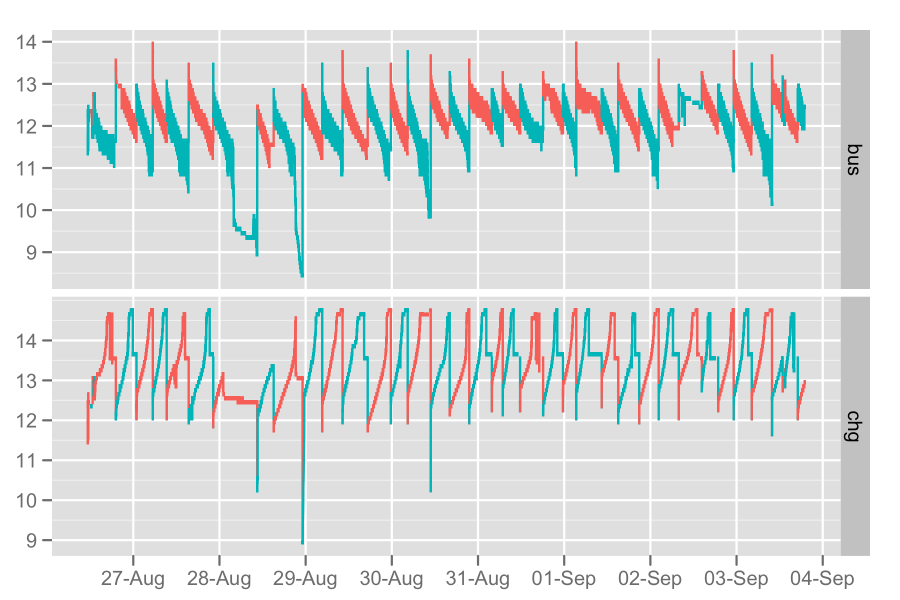
 The charging circuit worked pretty well. The idea here is that there are two batteries. One is connected to the bus which runs the Arduino, sensors, and pump. The other is connected to the AC charger. The Arduino controls relays which switch the batteries between the two. The upper line in the graph shows the voltage in the bus circuit. When the line is red, battery A is driving the bus. Each time a battery is switched into the bus circuit, it starts with about 13v, then voltage drops as it discharges.
What this graph shows is that the two circuits worked together. In each cycle, the charging circuit (on the bottom) got through the first phase (the slow ramp), then the second phase (the plateau at 14.8 volts), then the third trickle phase (the plateau at about 13.6 volts). When the bus circuit fell below 11 volts, the Arduino flipped the relays, reversing the batteries so the discharged one could charge, and vice-versa.
